Optical module receiving circuit and optical module

A receiving circuit and optical module technology, applied in the field of optical communication, can solve the problem of not being able to carry AMCC signals, etc., and achieve the effect of reducing impact and easy recovery

Inactive Publication Date: 2018-06-01
HISENSE BROADBAND MULTIMEDIA TECH
View PDF5 Cites 4 Cited by
  • Summary
  • Abstract
  • Description
  • Claims
  • Application Information

AI Technical Summary

Problems solved by technology

[0004] To realize the above AMCC functions, low-frequency signals need to be loaded on the service channel, but the current 10G EPON OLT optical module can only receive high-frequency digital service signals, and does not have the function of carrying AMCC signals

Method used


Image

  • Optical module receiving circuit and optical module
  • Optical module receiving circuit and optical module
  • Optical module receiving circuit and optical module

Examples


Embodiment Construction

[0017] The exemplary embodiments will be described in detail here, and examples thereof are shown in the accompanying drawings. When the following description refers to the accompanying drawings, unless otherwise indicated, the same numbers in different drawings represent the same or similar elements. The implementation manners described in the following exemplary embodiments do not represent all implementation manners consistent with the present invention. Rather, they are merely examples of devices and methods consistent with some aspects of the present invention as detailed in the appended claims.

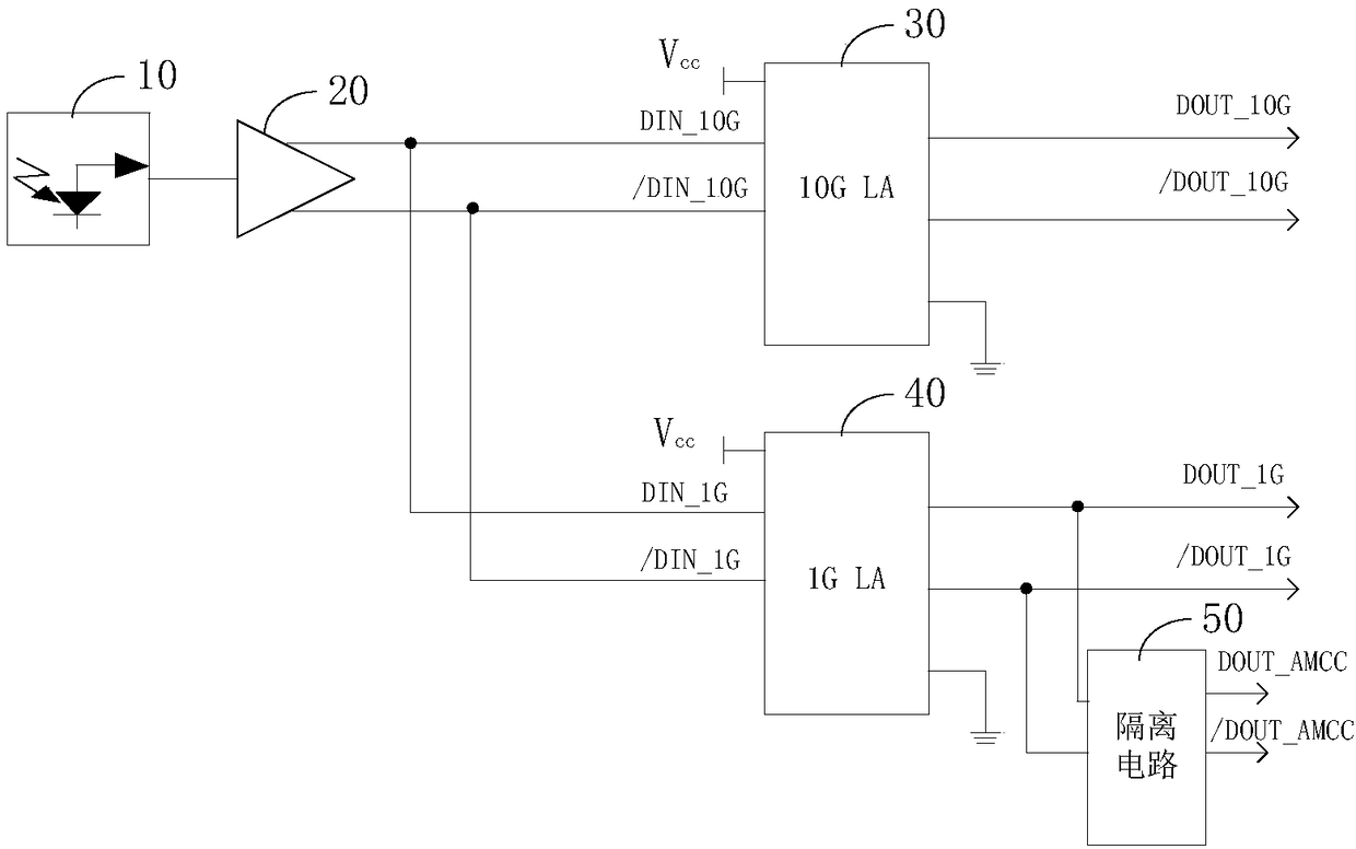
[0018] In order to realize the reception of AMCC control signals on the existing optical component receiving design without affecting the reception of service signals, the embodiment of the present invention provides an optical module receiving circuit and an optical module.

[0019] figure 1 It is a schematic structural diagram of an optical module receiving circuit provided by an ...


PUM


Abstract

The invention discloses an optical module receiving circuit and an optical module. According to the characteristic that a receiving circuit of a symmetric 10G EPON OLT optical module operates by employing a time division multiplexing mode, an output terminal of a 1G limiting amplifier is provided with an isolation circuit, 1G signals amplified by the 1G limiting amplifier are isolated by employingthe isolation circuit, AMCC signals amplified by the 1G limiting amplifier are gated, and the functions of receiving digital business signals and bearing the AMCC signals of the optical module are realized. According to the circuit design, on one hand, the amplitude of the 1G signals is higher than that of 10G signals and the transmission rate of the 1G signals is closer to the transmission rateof the AMCC signals so that the 1G signal business is amplified and the AMCC signals can also be amplified by employing the 1G limiting amplifier, the output AMCC signals thereof are more easily recovered, and the influence on the 1G business signals is less; on the other hand, the isolation circuit is arranged at the rear end of the 1G limiting amplifier so that the influence on the performance of the whole receiving circuit can be reduced, and the loss of the business signals is avoided.

Description

Technical field [0001] The present invention relates to the field of optical communication technology, in particular to an optical module receiving circuit and an optical module. Background technique [0002] In the optical communication network, the optical module realizes the conversion of optical signals into electrical signals and the conversion of electrical signals into electrical signals. Specifically, the received optical signal is converted into an electrical signal by the optical receiving sub-module in the optical module for further processing and identification; the high-speed electrical signal that needs to be sent is converted into light by the optical transmitting sub-module in the optical module. Signal and coupled to optical fiber for transmission. [0003] Among them, 10G EPON (Ethernet Passive Optical Network, Ethernet passive optical network) symmetric OLT (optical line terminal) optical module, as a smooth upgrade of 1G EPON and 10G EPON asymmetric OLT optical...

Claims


Application Information

Patent Timeline
Patent Type & Authority Applications(China)
IPC IPC(8): H04B10/60
CPCH04B10/60
Inventor 金成浩
Owner HISENSE BROADBAND MULTIMEDIA TECH
Why Eureka
Try Eureka