Pantograph carbon contact strip dip angle measuring and monitoring device and its method

A pantograph carbon slide and monitoring device technology, applied in the direction of measuring devices, current collectors, electric vehicles, etc., can solve problems such as scraping, inoperability, and carbon slide wear too fast, so as to ensure connection stability and achieve normal Driving and the effect of reducing railway accidents

Inactive Publication Date: 2018-06-05
DATONG XINCHENG NEW MATERIAL CO LTD
View PDF5 Cites 7 Cited by
  • Summary
  • Abstract
  • Description
  • Claims
  • Application Information

AI Technical Summary

Problems solved by technology

During the operation of the pantograph, the carbon slide plate will wear too fast. The bottom of the catenary section of many new railways is arc-shaped, and the surface of many contact wires is too hard, which will easily cause the wear of the carbon slide plate. A certain contact pressure is always required to ensure that the locomotive receives current in good condition. When the contact pressure is too small or even zero, the carbon slide of the pantograph will break away from the catenary and go offline. Sparks or arcs will be generated at the moment of offline, increasing the The electrical wear of the contact wire and the pantograph carbon slide shortens the service life; and the partial wear of the carbon slide is also one of the important reasons affecting the life of the carbon slide. The formation of grooves and stuck contact wires will cause bow scraping. The appearance of scraping bows will easily damage the pantograph, making the train power supply insufficient or directly unable to run, and even the pantograph will scrape the contact wire, so that the entire operating line cannot be powered, thus cause more damage

Method used


Image

  • Pantograph carbon contact strip dip angle measuring and monitoring device and its method
  • Pantograph carbon contact strip dip angle measuring and monitoring device and its method

Examples


Embodiment Construction

[0026] The following will clearly and completely describe the technical solutions in the embodiments of the present invention with reference to the accompanying drawings in the embodiments of the present invention. Obviously, the described embodiments are only some, not all, embodiments of the present invention. Based on the embodiments of the present invention, all other embodiments obtained by persons of ordinary skill in the art without making creative efforts belong to the protection scope of the present invention.

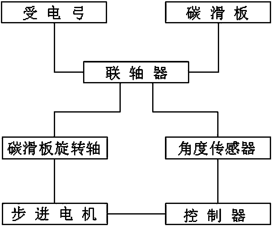
[0027] according to Figure 1-2 The device for measuring and monitoring the inclination of a pantograph carbon sliding plate includes a pantograph and a carbon sliding plate, and the pantograph and the carbon sliding plate are connected by a coupling, and the end of the coupling is connected with Carbon skateboard rotation shaft and angle sensor, the angle sensor is connected to the controller, the controller and the stepper motor are electrically connected th...


PUM


Abstract

The invention discloses a pantograph carbon contact strip dip angle measuring and monitoring device and its method. The pantograph carbon contact strip dip angle measuring and monitoring device comprises a pantograph and a carbon contact strip; the pantograph and the carbon contact strip are connected through a shaft joint, and the end part of the shaft joint is connected with a carbon contact strip rotating shaft and an angle sensor, the angle sensor is connected with the controller; the controller is electrically connected with a stepping motor through a communication interface, a steel ropeis arranged between the stepping motor and the carbon contact strip rotating shaft, the stepping motor and the carbon contact strip rotating shaft are in driving connection through the steel rope; the inner part of the controller is provided with a single chip, and a connecting end of the single chip is connected with a data processing module, a Bluetooth module, an alarm module and an automaticrouting inspection module. The pantograph carbon contact strip offset angle is provided with three threshold values which are normal level, alarm level and sudden stop level; the measurement time interval of the pantograph carbon contact strip is 0.1 second; the safety of high-speed train driving is greatly promoted.

Description

technical field [0001] The invention relates to the technical field of pantograph carbon slide plates of electric locomotives, in particular to a pantograph carbon slide plate inclination measuring and monitoring device and method thereof. Background technique [0002] With the development of the railway industry, there are more and more applications of high-speed railways and high-speed trains. Trains need to pass pantographs and carbon skateboards to obtain power from overhead cables. In recent years, railway accidents have occurred from time to time, causing a large number of casualties And huge economic losses, caused an irreparable situation to the country and the people, a large part of the reason is because the failure of the pantograph cannot be found in time. During the operation of the pantograph, the carbon slide plate will wear too fast. The bottom of the catenary section of many new railways is arc-shaped, and the surface of many contact wires is too hard, which...

Claims


Application Information

Patent Timeline
Patent Type & Authority Applications(China)
IPC IPC(8): B60L5/20G01B21/22
CPCY02T90/16B60L5/20G01B21/22
Inventor 武建军
Owner DATONG XINCHENG NEW MATERIAL CO LTD
Why Eureka
Try Eureka