Sintering machine blowing device capable of adjusting blowing starting point in self-adaptation manner and blowing method thereof

A self-adaptive adjustment and injection device technology, applied in the field of sintering, can solve problems such as loss of auxiliary effect, safety accidents, gas fire, etc., and achieve the effects of strengthening auxiliary sintering effect, huge development potential, and improving safety factor

Pending Publication Date: 2018-06-05
ZHONGYE-CHANGTIAN INT ENG CO LTD
View PDF0 Cites 0 Cited by
  • Summary
  • Abstract
  • Description
  • Claims
  • Application Information

AI Technical Summary

Problems solved by technology

[0006] The gas injection device in the prior art has the following defects in production because it cannot self-adaptively adjust the injection starting point:
Once such an abnormal working condition is encountered, the injection starting point originally designed by the gas injection device must be changed accordingly. Otherwise, when the gas is injected to the material surface, the combustion zone is still on the material surface, and the gas fire, causing a safety accide

Method used


Image

  • Sintering machine blowing device capable of adjusting blowing starting point in self-adaptation manner and blowing method thereof
  • Sintering machine blowing device capable of adjusting blowing starting point in self-adaptation manner and blowing method thereof
  • Sintering machine blowing device capable of adjusting blowing starting point in self-adaptation manner and blowing method thereof

Examples


Example Embodiment

[0067] According to the second embodiment provided by the present invention, a sintering machine injection method that can adaptively adjust the injection starting point is provided:

[0068] A sintering machine injection method capable of adaptively adjusting the starting point of injection or an injection method using the above-mentioned sintering machine injection device capable of adaptively adjusting the starting point of injection, the method comprising the following steps:

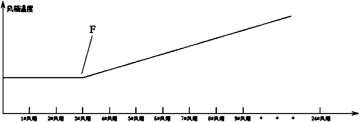
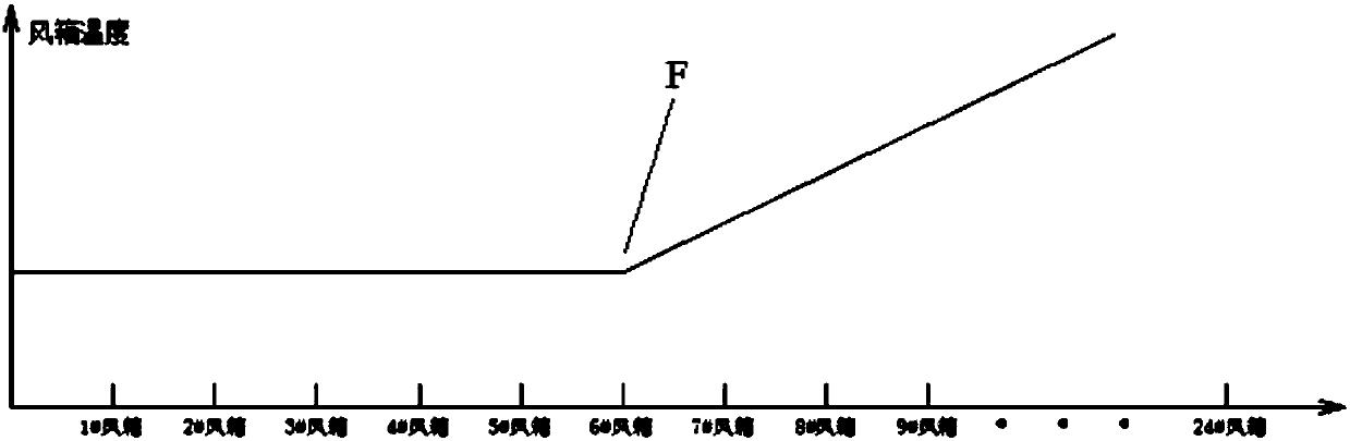
[0069] 1) The whole device starts to run, and the control system 9 monitors the temperature values ​​of each bellows 4 in real time through the bellows temperature measuring device 5, and organizes the bellows temperature curve according to the temperature values ​​of each bellows 4 measured by the bellows temperature measuring device 5. The position corresponding to the inflection point F is the best starting position for gas injection;

[0070] 2) During the real-time monitoring process, if the po...

Example Embodiment

[0077] Example 1

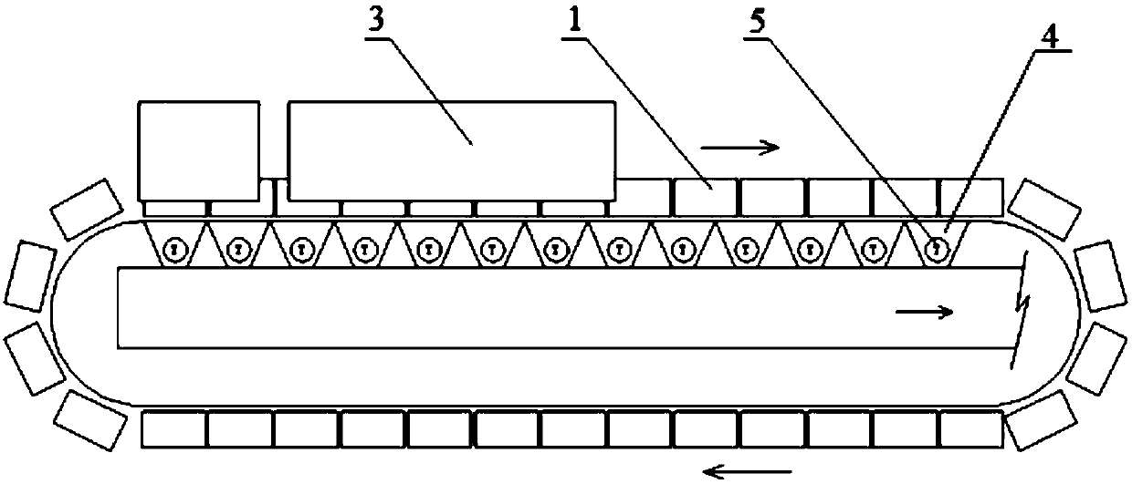
[0078] like Figure 1-4 , Figure 6-9 As shown, a sintering machine injection device that can adaptively adjust the injection starting point, the device includes a sintering machine trolley 1, an injection cover 2, and a gas injection device 3. The gas injection device 3 includes a gas injection main pipe 301 , a gas injection branch pipe 302 , and a gas injection pipe row 303 . The sintering machine trolley 1 is located in the blowing hood 2 . The gas injection main pipe 301 is arranged on the outside of the injection cover 2 . The row of gas injection pipes 303 is arranged above the sintering machine trolley 1 , and the row of gas injection pipes 303 is located in the injection hood 2 . One end of the gas injection branch pipe 302 is connected to the gas injection main pipe 301 and the other end is connected to the gas injection pipe row 303 . The gas injection pipe row 303 includes a plurality of gas injection pipes 304 . The gas injection pipe 304 ...

Example Embodiment

[0090] Example 2

[0091] like Figure 1-3 , Figure 5-9 As shown, a sintering machine injection device that can adaptively adjust the injection starting point, the device includes a sintering machine trolley 1, an injection cover 2, and a gas injection device 3. The gas injection device 3 includes a gas injection main pipe 301 , a gas injection branch pipe 302 , and a gas injection pipe row 303 . The sintering machine trolley 1 is located in the blowing hood 2 . The gas injection main pipe 301 is arranged on the outside of the injection cover 2 . The row of gas injection pipes 303 is arranged above the sintering machine trolley 1 , and the row of gas injection pipes 303 is located in the injection hood 2 . One end of the gas injection branch pipe 302 is connected to the gas injection main pipe 301 and the other end is connected to the gas injection pipe row 303 . The gas injection pipe row 303 includes a plurality of gas injection pipes 304 . The gas injection pipe 304 ...


PUM


Abstract

The invention discloses a sintering machine blowing device capable of adjusting blowing starting point in a self-adaptation manner. The device comprises a sintering machine trolley, a blowing cover and a gas blowing device, the gas blowing device comprises a gas blowing main pipe, a gas blowing branch pipe and a gas blowing pipe bundle, the sintering machine trolley is located in the blowing cover, the gas blowing main pipe is arranged on the outer side of the blowing cover, the gas blowing pipe bundle is arranged above the sintering machine trolley, the gas blowing pipe bundle is located in the blowing cover, one end of the gas blowing branch pipe is connected with the gas blowing main pipe, the other end of the gas blowing branch pipe is connected with the gas blowing pipe bundle, the gas blowing pipe bundle comprises multiple gas blowing pipes which are provided with gas blowing holes. The device is characterized in that multiple air boxes are arranged below the sintering machine trolley, and an air box temperature measuring device is arranged at the position, on each air box, of the lower portion of the sintering machine trolley. According to the device, the blowing starting point can be adjusted in the self-adaptation manner, defects in the prior art can be effectively overcome, safety coefficients can be improved, and the assisting effect is ensured.

Description

technical field [0001] The invention relates to a sintering machine gas injection device and a gas injection method thereof, in particular to a sintering machine injection device and a gas injection method capable of adaptively adjusting the injection starting point, and belongs to the field of sintering. Background technique [0002] The sintering process is a key link in the ironmaking process. Its principle is to mix various powdery iron-containing raw materials with an appropriate amount of fuel and flux, add an appropriate amount of water, mix and pelletize the material on the sintering equipment to make the material A series of physical and chemical changes, sintered into blocks, which are sent to the blast furnace for the next step. [0003] In order to reduce the coke ratio and smelting cost of blast furnace ironmaking, blast furnaces often require high strength and high reducibility for sinter. In the sintering process, the sintered ore is generally required to hav...

Claims


Application Information

Patent Timeline
IPC IPC(8): F27B21/08C22B1/16
CPCF27B21/00C22B1/16F27M2003/04
Inventor 周浩宇孙英
Owner ZHONGYE-CHANGTIAN INT ENG CO LTD
Why Eureka
Try Eureka