LED lamp circuit board soldering point inspection device

A technology of LED lamps and inspection devices, applied in measuring devices, material analysis through optical means, instruments, etc., can solve the problem of inability to lubricate the first movable block and the first screw rod, inability to improve the illuminance of the detection area, and inability to detect Comprehensive scope and other issues, to achieve the effect of saving fixed time, increasing the detection effect, and simple structure

Pending Publication Date: 2018-06-05
清远韶兴新能源科技有限公司
View PDF0 Cites 6 Cited by
  • Summary
  • Abstract
  • Description
  • Claims
  • Application Information

AI Technical Summary

Problems solved by technology

[0002] LED is called the fourth-generation lighting source or green light source, which has the characteristics of energy saving, environmental protection, long life, small size, etc., and is widely used in various indications, displays, decorations, backlights, general lighting and urban night scenes. Depending on the function, it can be divided into five categories: information display, signal lights, vehicle lamps, LCD backlight, and general lighting. Carry out inspections to ensure that there are no false soldering or missing soldering lamps. However, the LED lamp circuit board solder joint inspection devices currently on the market have simple structures and single functions. There is no vacuum pump, and the circuit board cannot be fixed by negative pressure adsorption. The first servo motor and the second servo motor cannot make the detection range more comprehensive through the first servo motor and the second servo motor, there is no curved reflector, the illuminance of the detection area cannot be improved through the curved reflector, and there is no refueling device , the lubricating device cannot be used to lubricate the space between the first movable block and the first screw rod

Method used


Image

  • LED lamp circuit board soldering point inspection device
  • LED lamp circuit board soldering point inspection device
  • LED lamp circuit board soldering point inspection device

Examples


Embodiment

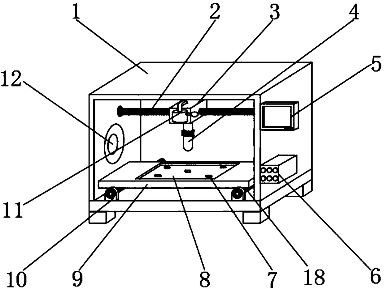
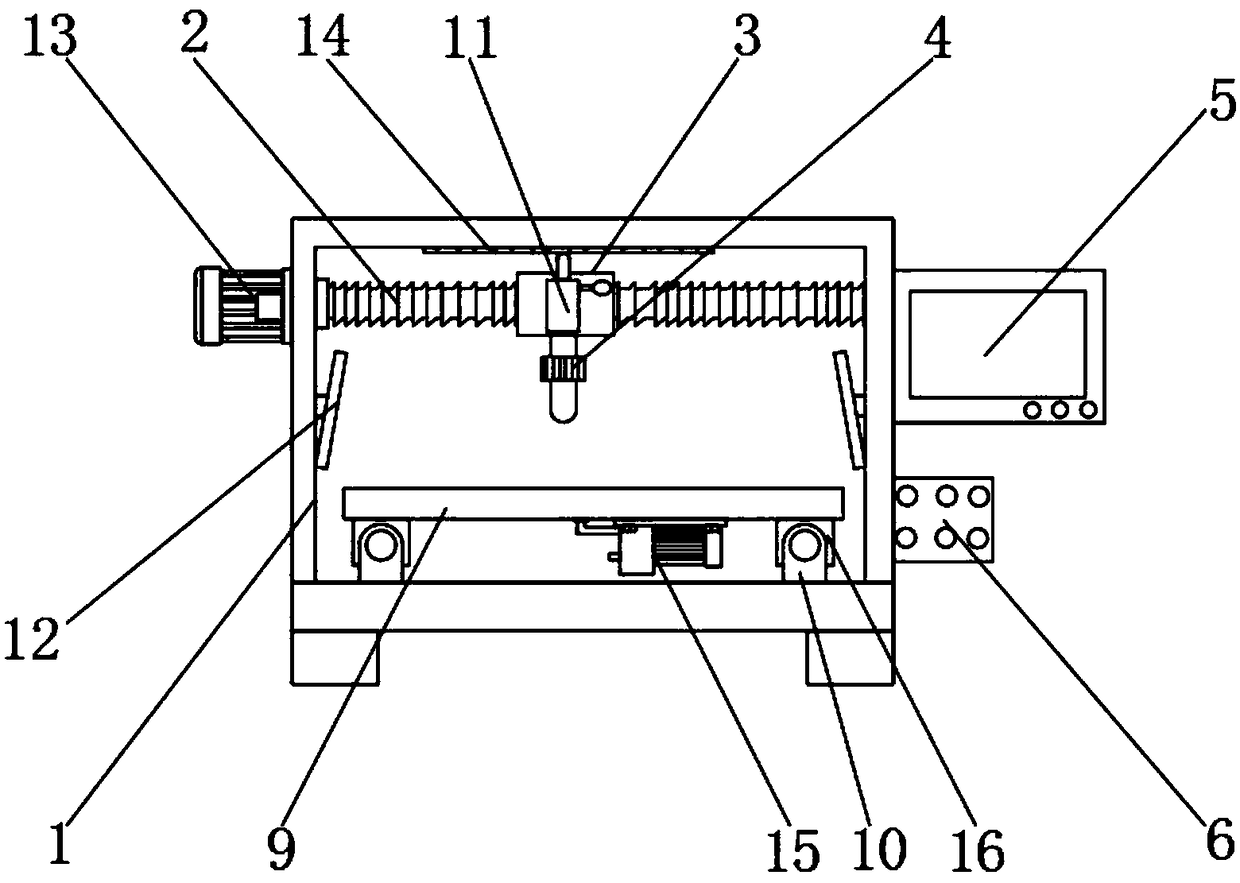
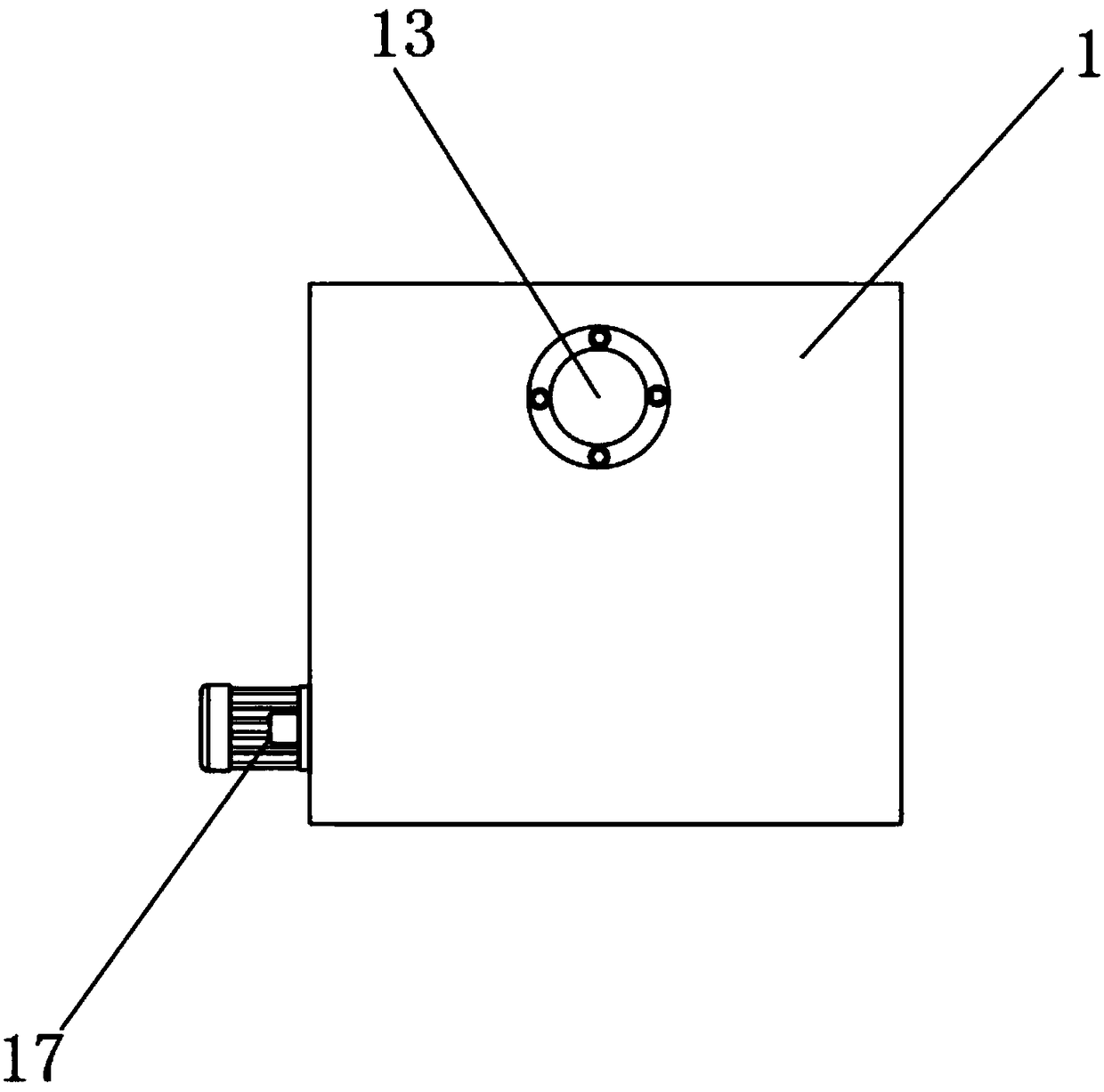
[0025] Example: refer to Figure 1-4 , the present invention provides a technical solution: a LED lamp circuit board solder joint inspection device, including a box 1, a first servo motor 13 is provided on one side of the box 1, and a display is provided on the other side of the box 1 5. A control switch 6 is provided on one side of the cabinet 1 close to the lower position of the display 5, and an LED light 14 is installed on the inner top of the cabinet 1, and a curved reflector 12 is provided on the inside of the cabinet 1, and the cabinet 1 The inner side of the box body 1 is provided with a first screw rod 2 corresponding to the position of the first servo motor 13, the inner bottom of the box body 1 is fixed with a connection block 10, and the rear side of the connection block 10 is provided at a position corresponding to the second servo motor 17. There is a second screw mandrel 18, a support plate 9 is arranged above the second screw mandrel 18, and a second movable bl...


PUM


Abstract

The invention discloses an LED lamp circuit board soldering point inspection device which comprises a box body, wherein a first servo motor is arranged on one side of the box body, a display screen isarranged on the other side of the box body, a control switch is arranged on one side, close to the inferior position of the display screen, of the box body, an LED lamp is arranged at the interior top end of the box body, and a curved surface reflector is arranged on the inner side of the box body. The LED lamp circuit board soldering point inspection device has a simple structure, is convenientto operate, economic and practical, the negative-pressure adsorption and fixation to the circuit board can be conducted through a vacuum pump arranged, the working flow can be optimized, the fixationtime can be saved, the working efficiency can be improved, fueling for lubrication is conducted between a first moving block and a first lead screw through a fueling device arranged, so as to reduce the friction of the two, reduce the wear and save the cost, and harsh noise caused easily due to excessive dryness between the first moving block and the first lead screw can be solved.

Description

technical field [0001] The invention relates to the technical field of an LED lamp circuit board solder joint inspection device, in particular to a LED lamp circuit board solder joint inspection device. Background technique [0002] LED is called the fourth-generation lighting source or green light source, which has the characteristics of energy saving, environmental protection, long life, small size, etc., and is widely used in various indications, displays, decorations, backlights, general lighting and urban night scenes. Depending on the function, it can be divided into five categories: information display, signal lights, vehicle lamps, LCD backlight, and general lighting. Carry out inspections to ensure that there are no false soldering or missing soldering lamps. However, the LED lamp circuit board solder joint inspection devices currently on the market have simple structures and single functions. There is no vacuum pump, and the circuit board cannot be fixed by negativ...

Claims


Application Information

Patent Timeline
Patent Type & Authority Applications(China)
IPC IPC(8): G01N21/88G01N21/01
CPCG01N21/8806G01N21/01G01N2021/0112
Inventor 吴慧华
Owner 清远韶兴新能源科技有限公司
Why Eureka
Try Eureka