
Impeller marginal line matching method and device

A matching method and matching device technology, applied in special data processing applications, instruments, electrical digital data processing, etc., can solve the problems of high computer resource requirements, long calculation cycle, inevitable use of numerical simulation, etc., to improve isentropy Efficiency, the effect of saving computing time and computing resources

Active Publication Date: 2018-06-05
AECC COMML AIRCRAFT ENGINE CO LTD
View PDF5 Cites 0 Cited by
  • Summary
  • Abstract
  • Description
  • Claims
  • Application Information

AI Technical Summary

Problems solved by technology

The above-mentioned first method will encounter the following problems in the process of finding the optimal timing position: 1. The current unsteady calculation may involve the blade reduction problem, and the process is cumbersome; 2. The unsteady calculation of multiple calculation examples requires computer resources. Higher; 3. Repeated iterations of numerical simulation are likely to cause long calculation cycles
Compared with the first method, the second method above reduces a lot of time and resource consumption, but it is still inevitable to use numerical simulation and consume computing resources

Method used


Image

  • Impeller marginal line matching method and device
  • Impeller marginal line matching method and device
  • Impeller marginal line matching method and device

Examples


Embodiment Construction

[0070] The present invention will be described in detail below. In the following paragraphs, different aspects of the embodiments are defined in more detail. The aspects so defined can be combined with any other aspect or aspects, unless it is clearly indicated that they cannot be combined. In particular, any feature considered to be preferred or advantageous may be combined with one or more other features considered to be preferred or advantageous.

[0071] The terms "first" and "second" appearing in the present invention are only for convenience of description, to distinguish different components with the same name, and do not indicate a sequence or a primary-secondary relationship.

[0072] In the description of the present invention, it should be understood that the terms "front", "rear", "circumferential", "axial" and "radial" indicate the orientation or positional relationship based on the orientation shown in the drawings. The or positional relationship is only for the con...


PUM


Abstract

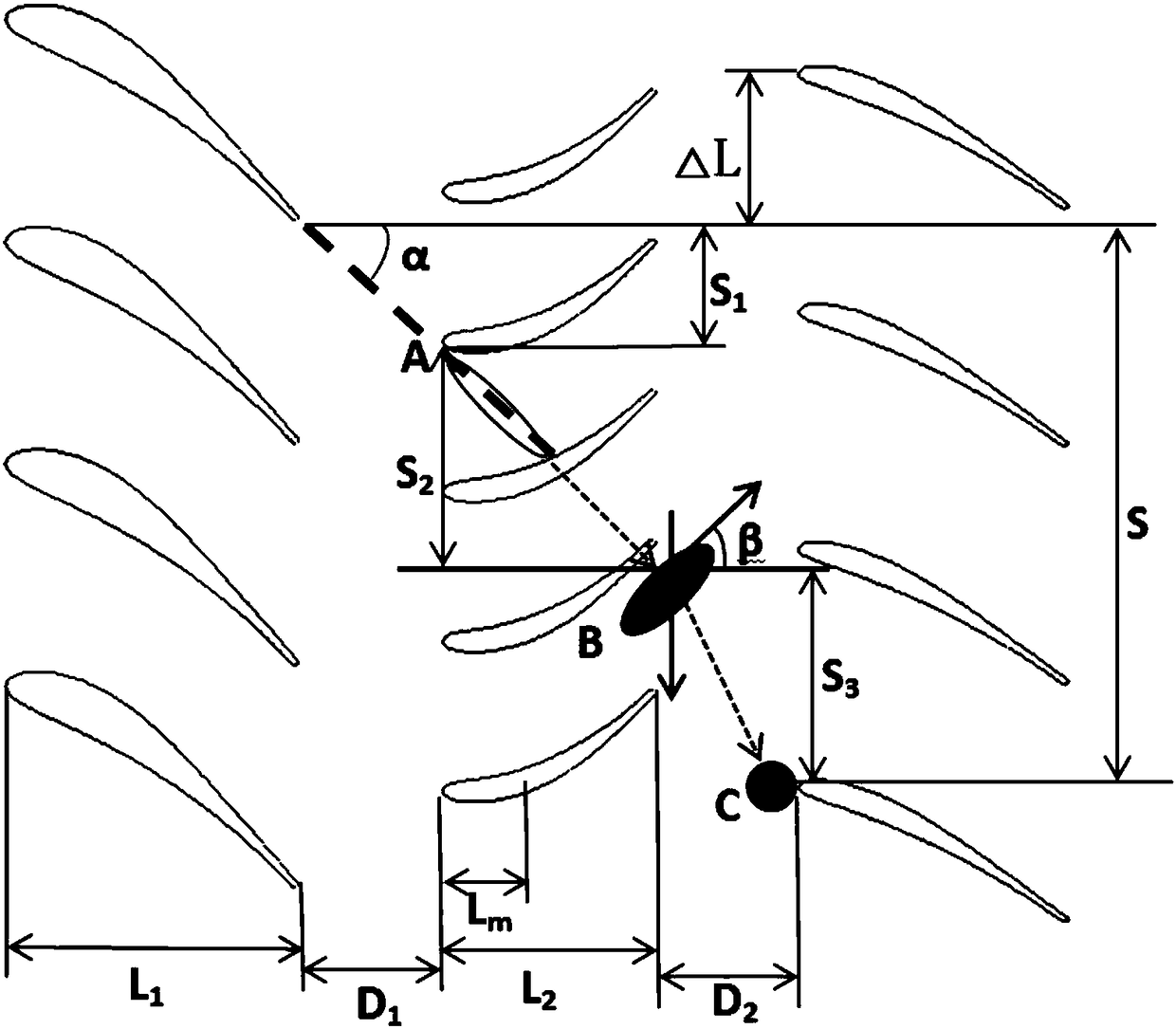
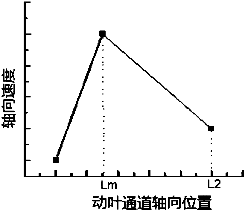
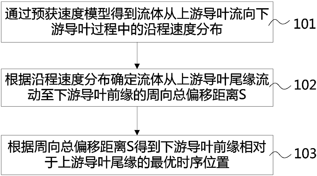
The invention relates to an impeller marginal line matching method and device. The impeller marginal line matching method comprises the following steps of: obtaining on-way speed distribution of a fluid flowing from an upstream guide vane to a downstream guide vane through a speed pre-obtaining model; determining a circumferential total offset distance of the fluid flowing the tail edge of the upstream guide vane to the front edge of the downstream guide value according to the on-way speed distribution; and obtaining an optimal time sequence position of the front edge of the downstream guide vane relative to the tail edge of the upstream guide value according to the circumferential total offset distance. According to the impeller marginal line matching method, optimal time sequence positions of impellers can be simply and rapidly searched, so that the process of carrying out analog calculation through numerical software is avoided, the calculation time and calculation resources can besaved, and the design efficiency can be improved.

Description

Technical field [0001] The invention relates to the technical field of impeller design, in particular to a method and device for matching the edge line of an impeller. Background technique [0002] The aerodynamic design of turbomachines generally pursues high aerodynamic performance, and with the development of design methods, more and more limitations of steady design appear. The internal flow field of the turbomachine is inherently highly unsteady, and fully exploiting the aerodynamic benefits brought by the unsteady effect is a new breakthrough. Utilizing the unsteady effect of the flow field by arranging the timing position of the impeller can further improve the isentropic efficiency of the impeller. [0003] Different timing positions have different effects on the isentropic efficiency of the turbine, and there is an optimal timing position. In order to find the optimal timing position, the optimal timing position of the impeller can be obtained by simulating the different...

Claims


Application Information

Patent Timeline
IPC IPC(8): G06F17/50
CPCG06F30/20G06F2111/06
Inventor 张宝李跃跃顾玉群严红明
Owner AECC COMML AIRCRAFT ENGINE CO LTD
Learn More