
Patsnap Eureka
For R&D, Patsnap Eureka makes reading and utilizing patents & technical documents easy.
Patsnap Eureka AIR
Designed for self-driven R&D workflows. Generate viable solutions, solve complex R&D challenges, empower your innovation with AI.

Patsnap Eureka Materials
Designed for material experts only. Revolutionize your material R&D, from search, analyze, to developing new materials.

TechResearch
Generate reliable direction feasibility study reports for your R&D in just a few steps.

TechSeek
Discover and master advanced knowledge NOW. Basics, ideas, possibilities, all at once.

TechMind
As an expert in R&D Theories, TechMind can generates customized viable solutions instantly.

TechRisk
Analyze your overall solution with one click, know your potential R&D risks in advance.

TechMonitor
Get weekly tech updates, stay abreast of the latest tech innovations and key insights.
High-power motor
A high-power, chassis technology, applied in electrical components, electromechanical devices, electric components, etc., can solve the problems of increased cost, low market acceptance of appearance, inability to save costs and improve efficiency, and achieve less interference and lower energy. The effect of reducing heat consumption and reducing heat
- Summary
- Abstract
- Description
- Claims
- Application Information
AI Technical Summary
Problems solved by technology
Method used
Image

Examples
Embodiment 1
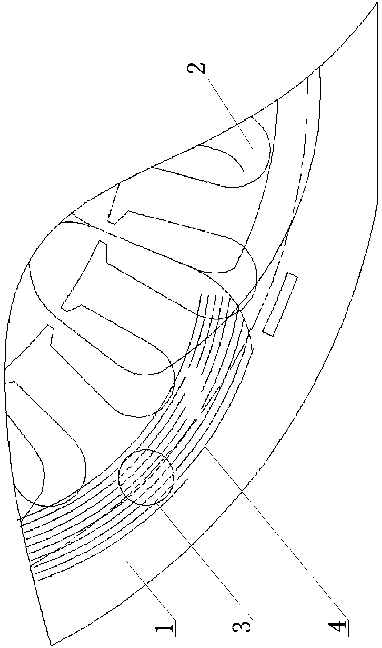
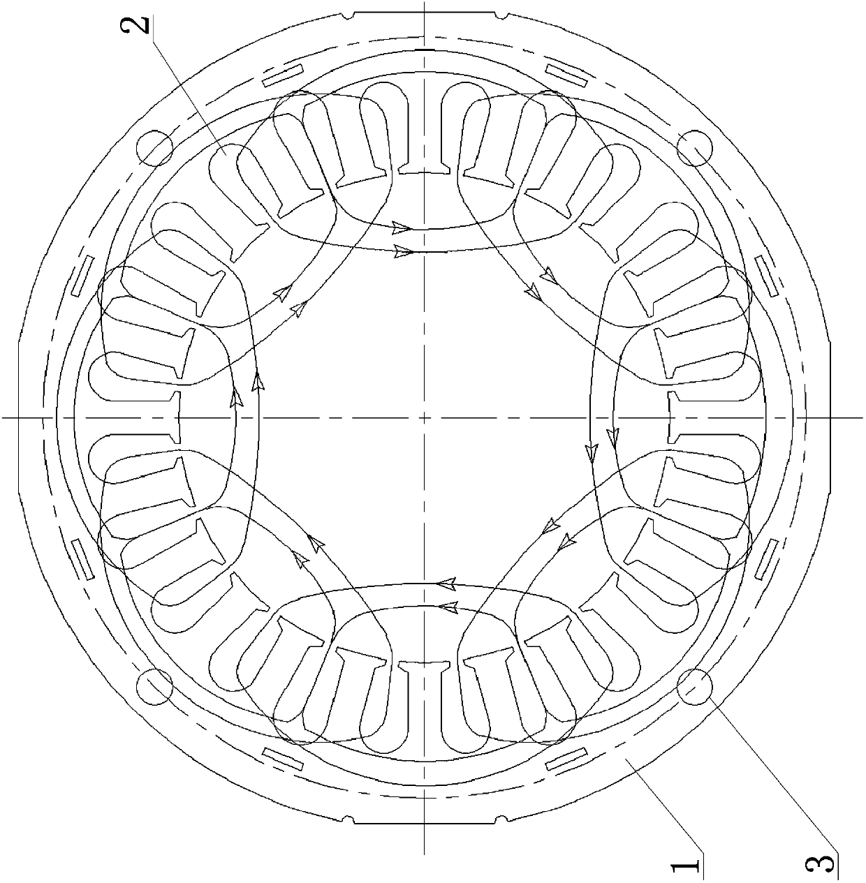
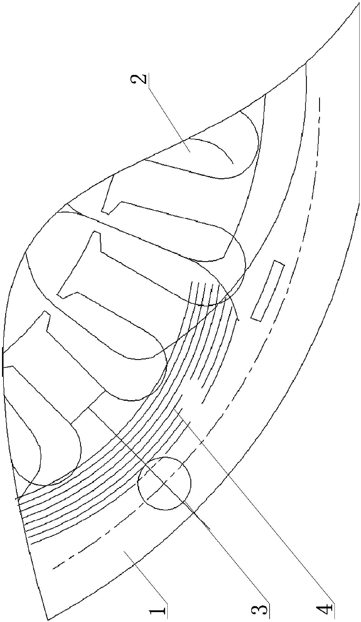
[0023] Such as figure 2 The high-power motor shown includes a cylindrical casing 1, the inner wall of the casing 1 has several evenly distributed winding slots 2, and at least four groups of evenly distributed electromagnetic coils are wound in the several winding slots 2, There are several screw holes 3 extending along its length direction on the casing 1, and several screw holes 3 are evenly distributed along the central axis of the casing 1, and each screw hole 3 is set corresponding to an electromagnetic coil, and the number of electromagnetic coils is the screw hole Integer multiples of 3, the magnetic force line 4 generated by the electromagnetic coil intersects the corresponding screw hole 3, such as image 3 As shown, its intersecting area is less than or equal to 10% of the total area of the screw holes 3.
[0024] Such as figure 2 As shown, the number of electromagnetic coils is twice the number of screw holes 3, there are eight sets of electromagnetic coils, a...
Embodiment 2
[0027] The structural principle of this embodiment is basically the same as the structural principle of Embodiment 1, the difference is that the number of electromagnetic coils is 1 times the number of screw holes 3, there are four groups of electromagnetic coils, and the number of screw holes 3 is four and is the same as that of the electromagnetic coils. One-to-one correspondence settings.
Embodiment 3
[0029] The structural principle of this embodiment is basically the same as the structural principle of Embodiment 1, the difference is that the number of electromagnetic coils is 1 times the number of screw holes 3, there are eight groups of electromagnetic coils, and the number of screw holes 3 is eight and the same as that of the electromagnetic coils. One-to-one correspondence settings.
PUM
 Abstract
Description
Claims
Application Information
 - R&D Engineer
- R&D Manager
- IP Professional
- Industry Leading Data Capabilities
- Powerful AI technology
- Patent DNA Extraction
Browse by: Latest US Patents, China's latest patents, Technical Efficacy Thesaurus, Application Domain, Technology Topic, Popular Technical Reports.
© 2024 PatSnap. All rights reserved.Legal|Privacy policy|Modern Slavery Act Transparency Statement|Sitemap|About US| Contact US: help@patsnap.com