
Closing device for preformed hole in artificial blood vessel and conveying device of closing device

A technology of artificial blood vessels and sealing devices, applied in the field of artificial blood vessels, can solve problems such as endoleaks, difficult to correct placement errors, and complicated operation of branch stents, and achieve the effects of improving effectiveness, sufficient sealing, and improving safety and reliability

Pending Publication Date: 2018-06-08
AORTEC MEDICAL TECH
View PDF0 Cites 2 Cited by
  • Summary
  • Abstract
  • Description
  • Claims
  • Application Information

AI Technical Summary

Problems solved by technology

However, the stent-grafts or repair devices on which the above-mentioned repair schemes rely have different defects. For example, in the bypass scheme, because the stent-graft completely seals the rupture area, it needs to increase the surgical trauma to open a new branch arterial opening, and the "chimney" scheme Due to the lack of sleeves in the covered stent, there is internal leakage, and the operation of the branch stent is complicated and it is difficult to correct the wrong placement.

Method used


Image

  • Closing device for preformed hole in artificial blood vessel and conveying device of closing device
  • Closing device for preformed hole in artificial blood vessel and conveying device of closing device

Examples


Embodiment Construction

[0036] Typical embodiments embodying the features and advantages of the present invention will be described in detail in the following description. It should be understood that the present invention can have various changes in different embodiments without departing from the scope of the present invention, and that the description and drawings therein are illustrative in nature and not intended to limit the present invention. invention.

[0037] In the following description of various exemplary embodiments of the invention, reference is made to the accompanying drawings, which form a part hereof, and in which are shown by way of example different exemplary structures, systems, and embodiments in which aspects of the invention may be implemented and steps. It is to be understood that other specific arrangements of components, structures, exemplary means, systems and steps may be utilized and structural and functional modifications may be made without departing from the scope o...


PUM

PropertyMeasurementUnit
Diameteraaaaaaaaaa
Diameteraaaaaaaaaa
Diameteraaaaaaaaaa

Abstract

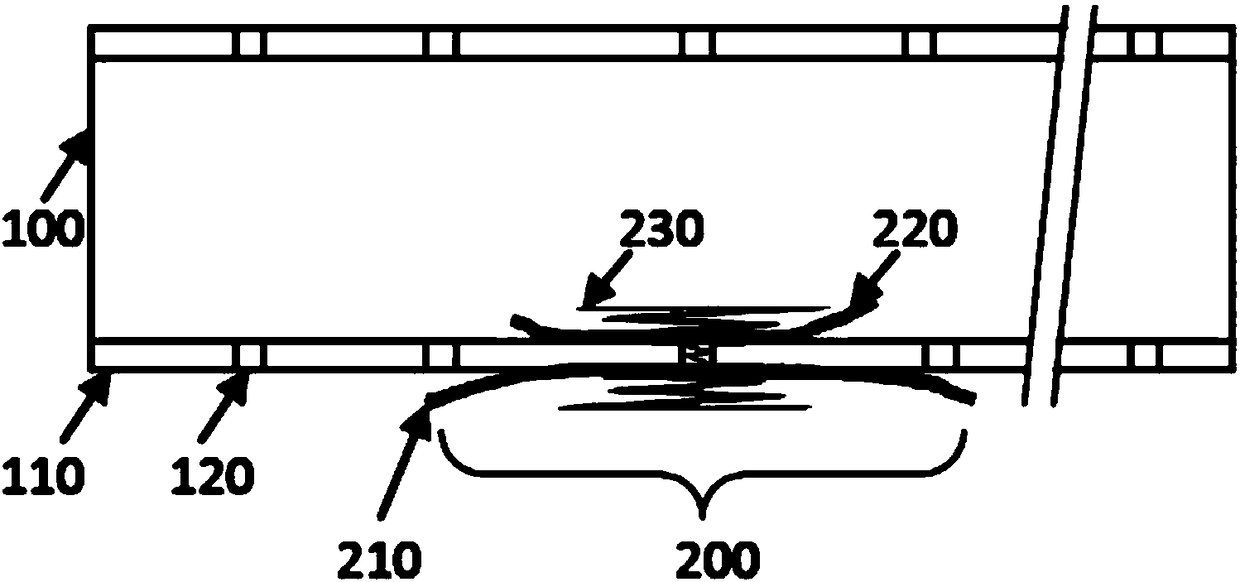
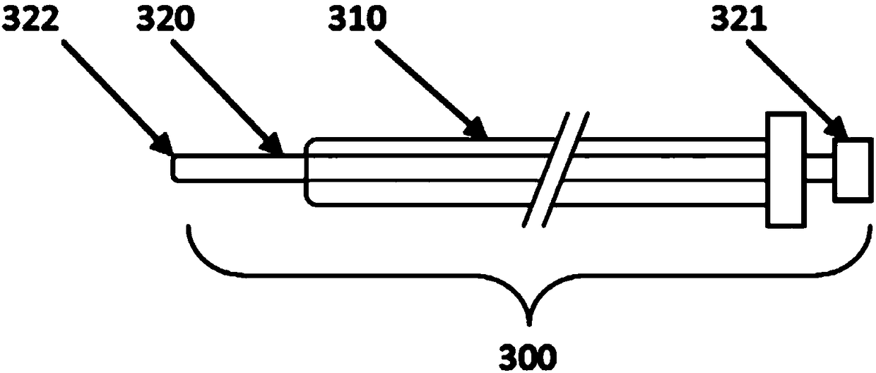
The invention discloses a closing device for a preformed hole in an artificial blood vessel and a conveying device of the closing device. The closing device comprises an outer side closing film, an inner side closing film and a positioning ring, wherein the positioning ring is of a spiral structure and comprises two end parts and a middle, the middle is connected between the two end parts, and thetwo end parts of the positioning ring are respectively connected to the outer side closing film and the inner side closing film. When the closing device is used for closing the preformed hole in theartificial blood vessel, the positioning ring penetrates through the preformed hole, and the outer side closing film and the inner side closing film are respectively located on the outer and inner sides of the pipe wall of the artificial blood vessel and correspond to the to-be-closed preformed hole. By utilizing the design that the outer side closing film and the inner side closing film are respectively located on the outer and inner sides of the pipe wall of the artificial blood vessel, the outer side closing film is selectively put into a false lumen on the outer side of an aortal artificial blood vessel, the inner side closing film is put into a true lumen on the inner side of the aortal artificial blood vessel, and the preformed hole and a breaking hole are closed together, so that the risk that openings of adjacent branched arteries are closed by the true lumen is avoided, meanwhile, the breaking hole is relatively adequately closed, and the validity and the safe reliability areimproved.

Description

technical field [0001] The invention relates to the technical field of artificial blood vessels, in particular to an artificial blood vessel reserved hole sealing device and a delivery device thereof. Background technique [0002] In the application of existing artificial blood vessel technology, stent grafts have been used as a means to repair aortic dissection. For the situation where the dissection rupture is located next to the opening of the branch artery, the preferred repair plan is to seal the dissection rupture and maintain the aortic dissection. Unobstructed blood flow in branch arteries. In this regard, some existing schemes include the use of stent grafts to seal the dissection rupture and adjacent branch arterial openings in the true lumen of dissection and the branch arterial bypass scheme, and the "chimney" scheme (that is, to place the graft in the true lumen of the dissection). The stent seals the opening of the dissection rupture and the opening of the adj...

Claims


Application Information

Patent Timeline
IPC IPC(8): A61F2/06A61B17/00
CPCA61B17/0057A61F2/064A61B2017/00623A61B2017/00654A61B2017/00597A61B2017/00601
Inventor 李潮
Owner AORTEC MEDICAL TECH
Learn More