Flue gas desulfurization and denitration device

A desulfurization, denitrification, and flue gas technology, which is applied in gas treatment, dispersed particle separation, membrane technology, etc., can solve problems such as the inability to meet the economics of flue gas treatment, and achieve low investment and construction costs, simple installation structure, and efficient desulfurization and denitrification. Effect

Pending Publication Date: 2018-06-08
BEIJING CPCEP ENERGY CONSERVATION & ENVIRONMENTAL PROTECTION TECH CO LTD
View PDF0 Cites 1 Cited by
  • Summary
  • Abstract
  • Description
  • Claims
  • Application Information

AI Technical Summary

Problems solved by technology

In view of the problems existing in the above-mentioned flue gas desulfurization and denitrification technology, it is obvious that the economical efficiency of the treatment of flue gas produced by medium and small boilers cannot be satisfied.

Method used


Image

  • Flue gas desulfurization and denitration device
  • Flue gas desulfurization and denitration device
  • Flue gas desulfurization and denitration device

Examples


Embodiment Construction

[0018] Embodiments of the technical solutions of the present invention will be described in detail below in conjunction with the accompanying drawings. The following examples are only used to illustrate the technical solutions of the present invention more clearly, and therefore are only examples, rather than limiting the protection scope of the present invention.

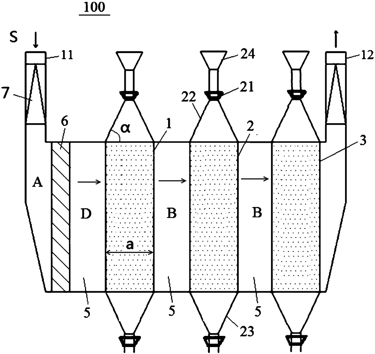
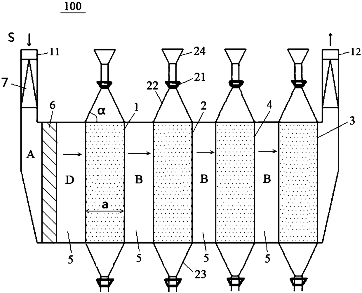
[0019] figure 1 A schematic structural diagram of a flue gas desulfurization and denitrification device 100 according to the present invention is shown. in such as figure 1 In the shown embodiment, the flue gas desulfurization and denitrification device 100 at least includes: in the initial state, a first reaction bed 1 filled with desulfurization materials and a second reaction bed 1 filled with denitrification materials are arranged at intervals along the flue gas flow channel in an initial state. Reaction bed 2 and unoccupied third reaction bed 3. Wherein, when the desulfurization material in the first reacti...


PUM


Abstract

The invention relates to the field of environmental protection technical equipment and discloses a flue gas desulfurization and denitration device. The flue gas desulfurization and denitration deviceat least comprises a first reaction bed filled with a desulfurization material, a second reaction bed filled with a denitration material and a vacant third reaction bed, wherein the first reaction bed, the second reaction bed and the vacant third reaction bed are sequentially arranged at intervals along a flue gas flow channel in an initial state. When the desulfurization material in the first reaction bed reacts with flue gas to reach a saturated state, the first reaction bed can form a vacant state, the third reaction bed can be configured to be filled with the denitration material, and thesecond reaction bed can be configured to be filled with the desulfurization material; and when the desulfurization material in the second reaction bed continuously reacts with the flue gas to reach asaturated state, the first reaction bed can be configured to be filled with the desulfurization material, and the second reaction bed at least can form a saturated state. The flue gas desulfurizationand denitration device disclosed by the invention can realize efficient desulfurization and denitration of the flue gas and is more economical for the treatment of the flue gas.

Description

technical field [0001] The invention relates to the field of environmental protection technical equipment, in particular to a flue gas desulfurization and denitrification device. Background technique [0002] At present, my country's domestic flue gas desulfurization and denitrification technology is still dominated by the traditional limestone / gypsum desulfurization combined with selective catalytic reduction (SCR) denitrification. Since this method uses two technologies, it needs to be equipped with two sets of equipment, and it needs to be equipped with The additional dust removal device leads to a large floor area, high investment and operating costs, and the problem of secondary pollution such as waste water and slag will be generated after the flue gas purification treatment. [0003] At present, my country mainly adopts medium and small boilers to meet the heating needs of users. For the construction of such medium and small boiler systems, not only environmental prote...

Claims


Application Information

Patent Timeline
IPC IPC(8): B01D53/75B01D53/50B01D53/56
CPCB01D53/50B01D53/56B01D53/75B01D2258/0283
Inventor 韩玉维马志刚王巧真江浩单选户白云峰初炜任绍华刘洋姜圆刘亚王天博王大龙徐大融
Owner BEIJING CPCEP ENERGY CONSERVATION & ENVIRONMENTAL PROTECTION TECH CO LTD
Why Eureka
Try Eureka