Integrated system for sintering ore cooling and sintering flue gas waste heat power generation, desulfurization and denitration

A technology for sintering flue gas and waste heat power generation. It is applied in lighting and heating equipment, waste heat treatment, and treatment of discharged materials. It can solve the problems of rising operating costs, high operating costs, and high investment costs, and achieve high-efficiency recovery, high-efficiency desulfurization and denitrification. , Solve the effect of high air leakage rate

Pending Publication Date: 2019-06-14
TONGFANG ENVIRONMENT +1
View PDF0 Cites 0 Cited by
  • Summary
  • Abstract
  • Description
  • Claims
  • Application Information

AI Technical Summary

Problems solved by technology

The operating costs are high, especially the denitrification process, whether it is ozone or flue gas heating, requires the use of a large amount of resources, resulting in an increase in operating costs
However, many enterprises focus on the dry simultaneous desulfurization and denitrification process, and there are also problems of high investment costs and high operating costs.

Method used


Image

  • Integrated system for sintering ore cooling and sintering flue gas waste heat power generation, desulfurization and denitration
  • Integrated system for sintering ore cooling and sintering flue gas waste heat power generation, desulfurization and denitration

Examples


Embodiment Construction

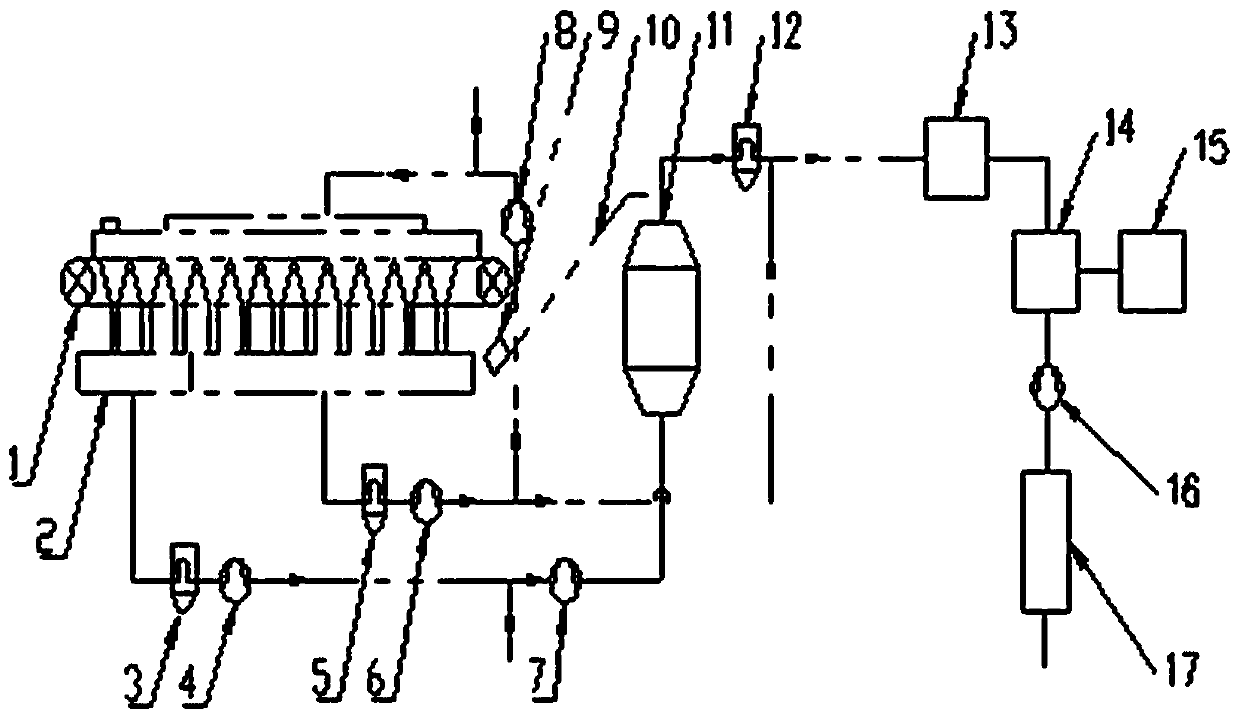
[0016] see figure 1 , the integrated system of sinter cooling and sintering flue gas waste heat power generation desulfurization and denitration integrated system of the present invention includes a sintering machine 1, a vertical cold kiln 11 connected in sequence, a multi-tube dust collector 12, an SCR denitrification reactor 13, a waste heat boiler 14, induced draft fan 16 and desulfurization tower 17. Between the sintering machine 1 and the vertical cooling kiln 11, an inclined winch 10 with a trolley 9 is arranged, and the temperature of the sintering hot ore at the outlet of the sintering machine 1 is 650°C to 750°C. The high-temperature steam outlet of the waste heat boiler 14 is connected to a generator set 15 . Below the sintering machine 1 is a partition bellows 2. The partition bellows 2 include a low-temperature flue gas outlet and a sub-low temperature flue gas outlet. The temperature of the low-temperature flue gas is ≤90°C, and the temperature of the sub-low te...


PUM


Abstract

The invention discloses an integrated system for sintering ore cooling and sintering flue gas waste heat power generation, desulfurization and denitration, and relates to sintering ore cooling and sintering sensible heat recovery technology. The integrated system for sintering ore cooling and sintering flue gas waste heat power generation, desulfurization and denitration comprises a sintering machine, a vertical cooling kiln, a multi-tube dust collector II, an SCR denitration reactor, a waste heat boiler, an induced draft fan and a desulfurization tower, wherein the vertical cooling kiln, themulti-tube dust collector II, the SCR denitration reactor, the waste heat boiler, the induced draft fan and the desulfurization tower are connected in sequence. An inclined windlass with a trolley isarranged between the sintering machine and the vertical cooling kiln. A high-temperature steam outlet of the waste heat boiler is connected to a generator set. A separation air box is arranged below the sintering machine, and a low-temperature flue gas outlet of the separation air box is sequentially connected to the bottom of the vertical cooling kiln through a multi-tube dust collector I, an exhaust fan I and an air blower; a sub-low temperature flue gas outlet of the separation air box is divided into two paths after passing through an electric dust collector and an exhaust fan II in sequence, one of the two paths is connected to an air outlet of the multi-tube dust collector II, and the other path returns to the material surface at the top of the sintering machine through a circulatingfan. According to the integrated system for sintering ore cooling and sintering flue gas waste heat power generation, desulfurization and denitration, a sintering ore closed cooling process is adopted, the temperature of hot air is increased, and sintering flue gas is simultaneously subjected to high-efficiency desulfurization and denitration, so that high-efficiency recycling of sensible heat ofthe sintering ore is achieved.

Description

technical field [0001] The invention relates to the technical fields of sinter cooling and sintering sensible heat recovery in the iron and steel industry, and desulfurization and denitrification of sintering flue gas, in particular to an integrated system for sintering cooling and sintering flue gas waste heat power generation desulfurization and denitrification. Background technique [0002] The energy consumption of the sintering process in the iron and steel production process is the second largest energy-consuming process, accounting for about 11%-20% of the total energy consumption, second only to ironmaking. During the sintering process, the sintered ore emits a large amount of heat, accounting for about 1 / 3 of the total energy consumption of sintering. This part of the energy recovery efficiency is very low and the waste is huge. There is a deep excavation space for resource recovery. [0003] At present, three forms are commonly used for cooling sintered ore: one is...

Claims


Application Information

Patent Timeline
Patent Type & Authority Applications(China)
IPC IPC(8): F27D17/00F27D15/02
CPCY02P10/25
Inventor 邵小珍王玉萍肖海涛岳勇
Owner TONGFANG ENVIRONMENT
Why Eureka
Try Eureka