A method for concentrated and efficient desulfurization and denitrification of sintering flue gas

A technology for desulfurization and denitrification and sintering flue gas, which is applied in the field of sintering flue gas desulfurization and denitrification, concentrated and efficient desulfurization and denitrification of sintering flue gas, can solve the problems of desulfurization and denitrification incompatibility, reduce flue gas treatment capacity, catalyst poisoning, etc., and achieve reduction of flue gas The effect of processing capacity, reducing investment cost and reducing operating cost

Active Publication Date: 2020-03-24
CENT SOUTH UNIV
View PDF7 Cites 0 Cited by
  • Summary
  • Abstract
  • Description
  • Claims
  • Application Information

AI Technical Summary

Problems solved by technology

[0008] Aiming at the incompatibility of desulfurization and denitrification in the existing sintering flue gas desulfurization combined with SCR denitrification process, such as high energy consumption in desulfurization followed by denitrification, catalyst poisoning in desulfurization after denitrification, the purpose of the present invention is to provide a sintering A method for concentrated and efficient desulfurization and denitrification of flue gas, which uses SO 2 NOx and NOx are discharged in specific areas of the sintering machine, and desulfurization and denitrification are carried out separately. While reducing the treatment capacity of flue gas, the compatibility of desulfurization and denitrification can be realized, so that the flue gas can be economically and efficiently treated on the basis of the existing desulfurization process. Efficient denitrification

Method used


Image

  • A method for concentrated and efficient desulfurization and denitrification of sintering flue gas
  • A method for concentrated and efficient desulfurization and denitrification of sintering flue gas

Examples


Embodiment 1

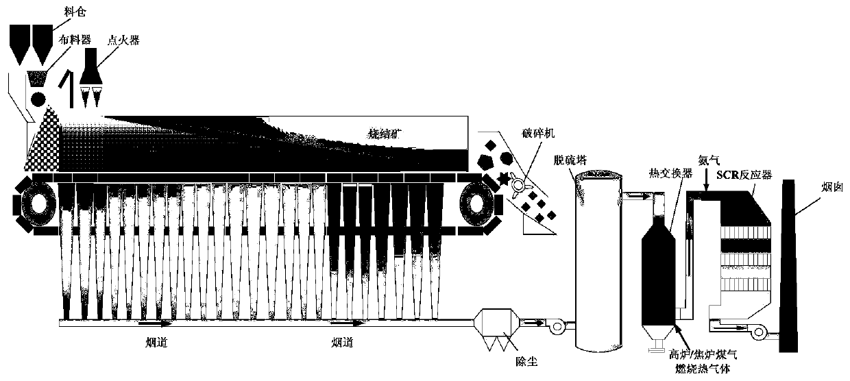
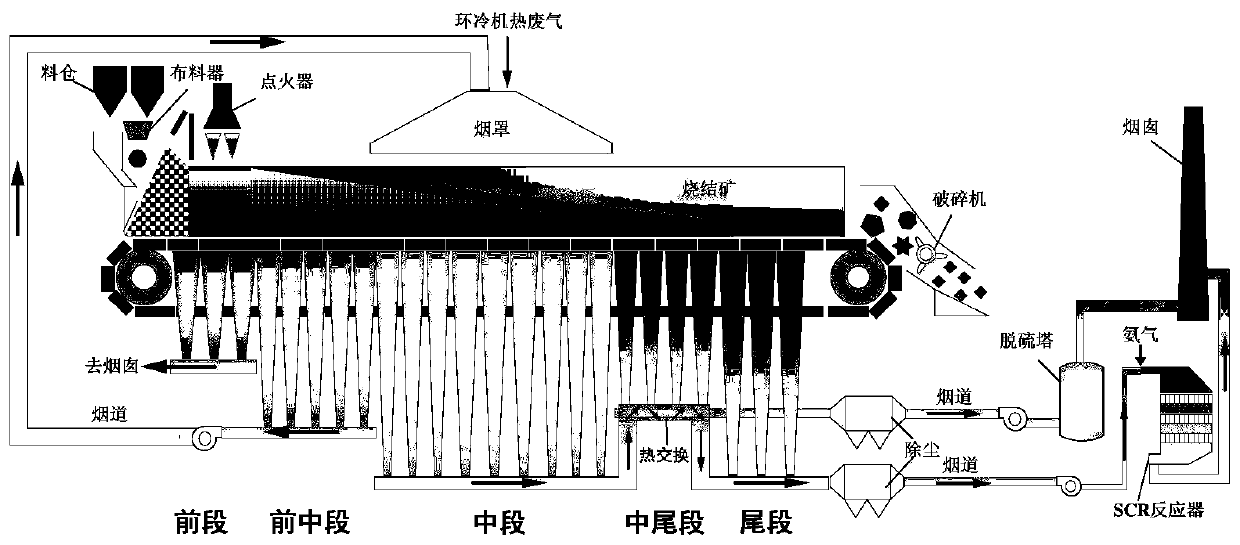
[0028] The sintering machine is divided into five parts along the length direction (that is, the material feeding end to the discharging end), the front section, the front middle section, the middle section, the middle tail section and the tail section. The length ratio is 3:5:9:4:3. The sintering process Medium, the front-end smoke particulate matter ≤ 20mg / Nm 3 , SO 2 ≤50mg / Nm 3 , NOx≤100mg / Nm 3 , it can be directly discharged into the chimney, and the front and middle sections are circulated to the material surface of the sintering machine for recycling. 2 The content is 17%, the temperature is 110℃; the flue gas NOx in the middle section is more than 200mg / Nm 3 , after heat exchange with the flue gas in the middle and tail sections, the temperature is raised to 120 °C, and then combined with the flue gas in the tail section, the temperature is increased to 250 °C, after dust removal, it enters the denitrification device to denitrify by SCR, and finally the flue gas reac...


PUM


Abstract

The invention discloses a concentrated efficient desulfurization and denitration method for the sintering flue gas. The flue gas of a sintering machine is sequentially divided into five parts of a front section, a front middle section, a middle section, a middle tail section and a tail section from the feeding end to the discharging end, the flue gas in the front middle section is recycled, NOx isemitted to the flue gas in the middle section of the sintering machine in a concentrated manner, the high-NOx flue gas in the middle section and the flue gas in the middle tail section exchange heatthrough a heat exchanger and join with the high-temperature flue gas in the tail section, the temperature of the flue gas is higher than 250 DEG C, and the requirement of the SCR denitration is met. The heat-exchanged high-SOx flue gas in the middle tail section of the sintering machine is desulfurized. The desulfurized flue gas and the denitrated flue gas are combined with the flue gas in the front section of the sintering machine, and are emitted through a chimney. According to the method, the SOx and the NOx are enriched in a specific area and are desulfurized and denitrated in a concentrated manner, so that the handling capacity of the flue gas is greatly reduced, and the treatment cost of pollutants is lowered.

Description

technical field [0001] The invention relates to a method for desulfurization and denitrification of sintering flue gas, in particular to a method for centralized and efficient desulfurization and denitrification of sintering flue gas, and belongs to the technical field of comprehensive treatment of iron and steel metallurgy flue gas. Background technique [0002] Under the background of global warming and deterioration of the ecological environment, the "low carbon economy" based on low energy consumption and low pollution has become the focus of global attention. The iron and steel industry is the basic industry in my country's industrial system, but it is also a typical high-energy-consuming and high-polluting industry. Its energy consumption accounts for about 15.25% of the energy consumption of the entire industrial sector; its exhaust gas emissions account for 16% of the country's total industrial emissions; The pollutant load emitted accounts for about 10% of the total ...

Claims


Application Information

Patent Timeline
Patent Type & Authority Patents(China)
IPC IPC(8): B01D53/90B01D53/81B01D53/56B01D53/50
CPCB01D53/50B01D53/81B01D53/8628B01D53/90B01D2251/2062B01D2258/0283
Inventor 范晓慧甘敏季志云吕薇汪国靖陈许玲姜涛李光辉袁礼顺黄柱成杨永斌郭宇峰张元波李骞朱忠平许斌邓琼赵元杰曹风张一雄肖恒
Owner CENT SOUTH UNIV
Why Eureka
Try Eureka