Clamping device for workpiece punching

A clamping device and punching technology, which is applied in the field of clamping devices for punching workpieces, and can solve problems such as low punching rate

Active Publication Date: 2018-06-08
徐州天骋智能科技有限公司
View PDF7 Cites 2 Cited by
  • Summary
  • Abstract
  • Description
  • Claims
  • Application Information

AI Technical Summary

Problems solved by technology

[0005] The purpose of the present invention is to provide a clamping device for workpiece punching, ...

Method used


Image

  • Clamping device for workpiece punching

Examples


Embodiment Construction

[0020] The following is further described in detail through specific implementation methods:

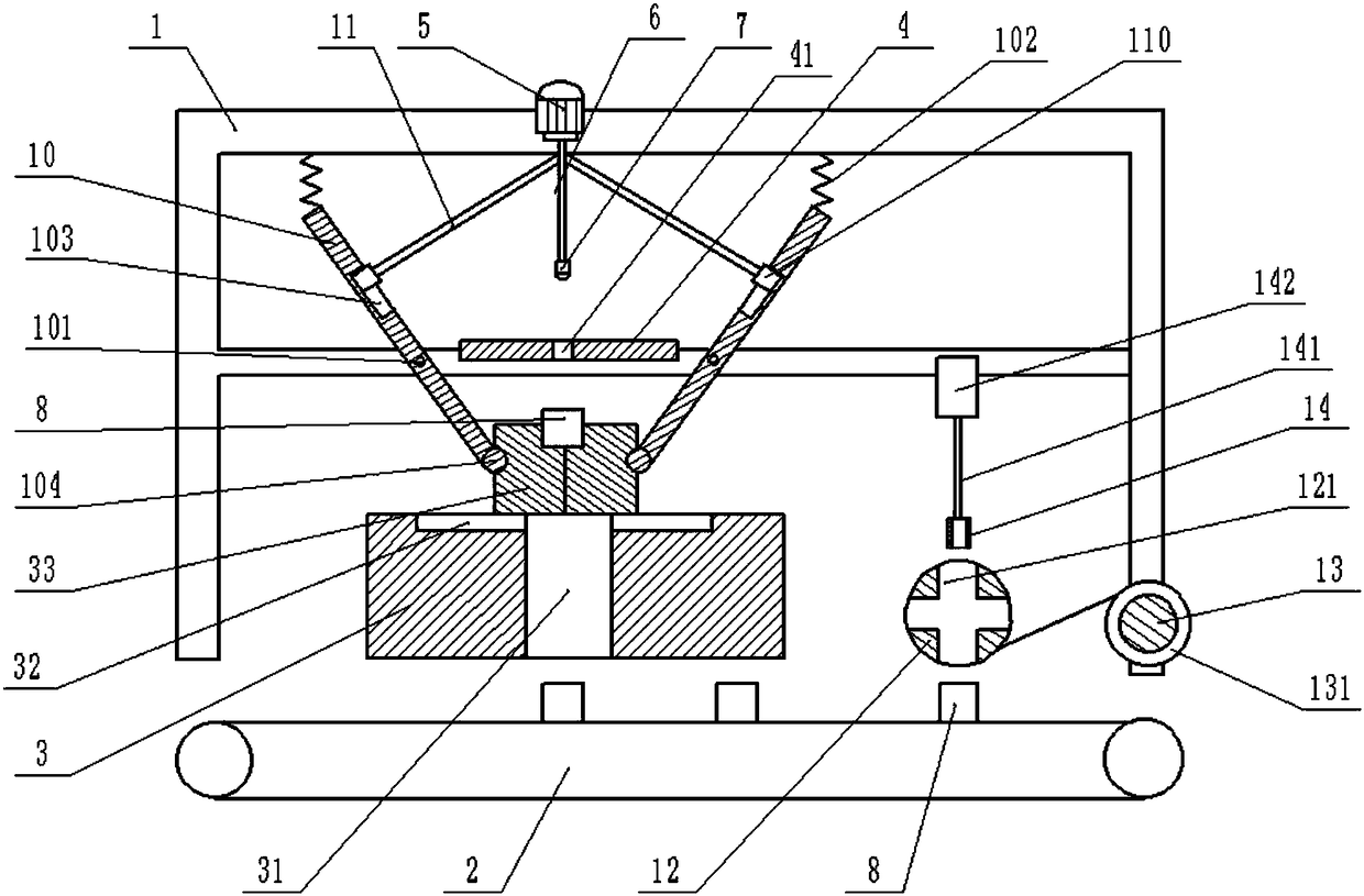
[0021] The reference signs in the drawings of the description include: frame 1, conveyor belt 2, base 3, discharge hole 31, chute 32, clamp block 33, positioning plate 4, positioning hole 41, first cylinder 5, first piston rod 6. Punch 7, punching die 8, first push rod 10, hinge point 101, spring 102, groove 103, ball head 104, second push rod 11, slider 110, film sticking roller 12, communication hole 121, Unwinding roller 13, film roll 131, film sticking column 14, second piston rod 141, second cylinder 142.

[0022] The embodiment is basically as attached figure 1 Shown:

[0023] A fixture for punching a workpiece, including a frame 1, a punching unit and a film sticking unit, wherein:

[0024] The punching station includes a conveyor belt 2, a base 3, a clamping part, a positioning plate 4 and a punching machine. The upper surface of the conveyor belt 2 is covered with a layer...


PUM


Abstract

The invention relates to the technical field of punching, in particular to a clamping device for workpiece punching. The device comprises a rack and a punching unit. The punching unit sequentially comprises a conveyor belt, a base, a clamping part, and a positioning plate and a punching machine fixed to the rack, a discharging hole and sliding grooves are formed in the upper surface of the base, the sliding grooves are formed in the two relative sides of the discharging hole and communicated with the discharging hole, the clamping part comprises two clamping units symmetric about the center line of the discharging hole, and each clamping unit comprises a clamping block, a first push rod and a second push rod, wherein the clamping block is arranged on the base, the middle section of the first push rod is hinged to the rack, one end of the first push rod is connected with a bulb of the clamping block, a spring is connected to the other end of the first push rod, the spring is verticallyfixed to the rack, and a groove is formed in the end, close to the spring, of the first push rod; one end of the second push rod is fixedly connected with an air cylinder, a sliding block is arrangedat the other end of the second push rod, and the sliding block is slidably arranged inside the groove. The technical problem that in the punching process, the punching rate is low due to sliding of workpieces in the punching process is solved.

Description

technical field [0001] The invention relates to the technical field of punching, in particular to a clamping device for punching a workpiece. Background technique [0002] At present, when the punching machine processes the workpiece, the workpiece often needs to be clamped by the clamping device before it can be punched. There are many types of existing workpiece clamping devices, the scope of application is small, and its structure is complicated, the operation is cumbersome, and the work efficiency is low. Low, the workpiece clamping is unreliable, which greatly affects the subsequent processing quality or assembly quality of the workpiece, thus causing unnecessary economic losses. [0003] In order to solve the above problems: the Chinese patent application number CN201520954070.0 discloses a punching machine clamping device, which includes a punching machine body and a clamping platform, and also includes a clamping arm and a clamping block. The pressing block is movab...

Claims


Application Information

Patent Timeline
IPC IPC(8): B21D43/00B21D28/24B65B33/02
CPCB21D28/24B21D43/003B65B33/02
Inventor 寇瑞东
Owner 徐州天骋智能科技有限公司
Why Eureka
Try Eureka