
Structure of a crankcase ventilation system for a supercharged engine

A technology for crankcase ventilation and supercharging engine, which is applied in crankcase ventilation, engine components, machines/engines, etc., can solve the problems of reduced engine adaptability and high manufacturing cost, avoid redundant design, and achieve high reliability and durability. Effect

Active Publication Date: 2020-04-07
DONGFENG MOTOR CORP HUBEI
View PDF5 Cites 0 Cited by
  • Summary
  • Abstract
  • Description
  • Claims
  • Application Information

AI Technical Summary

Problems solved by technology

However, the manufacturing cost of the three-way crankcase ventilation system is relatively high, and an additional pipeline is required to connect the crankcase and the air filter outlet, which reduces the adaptability of the engine.

Method used


Image

  • Structure of a crankcase ventilation system for a supercharged engine

Examples


Embodiment Construction

[0017] The present invention will be further described in detail below in conjunction with the accompanying drawings and specific embodiments to facilitate a clear understanding of the present invention, but they do not limit the present invention.

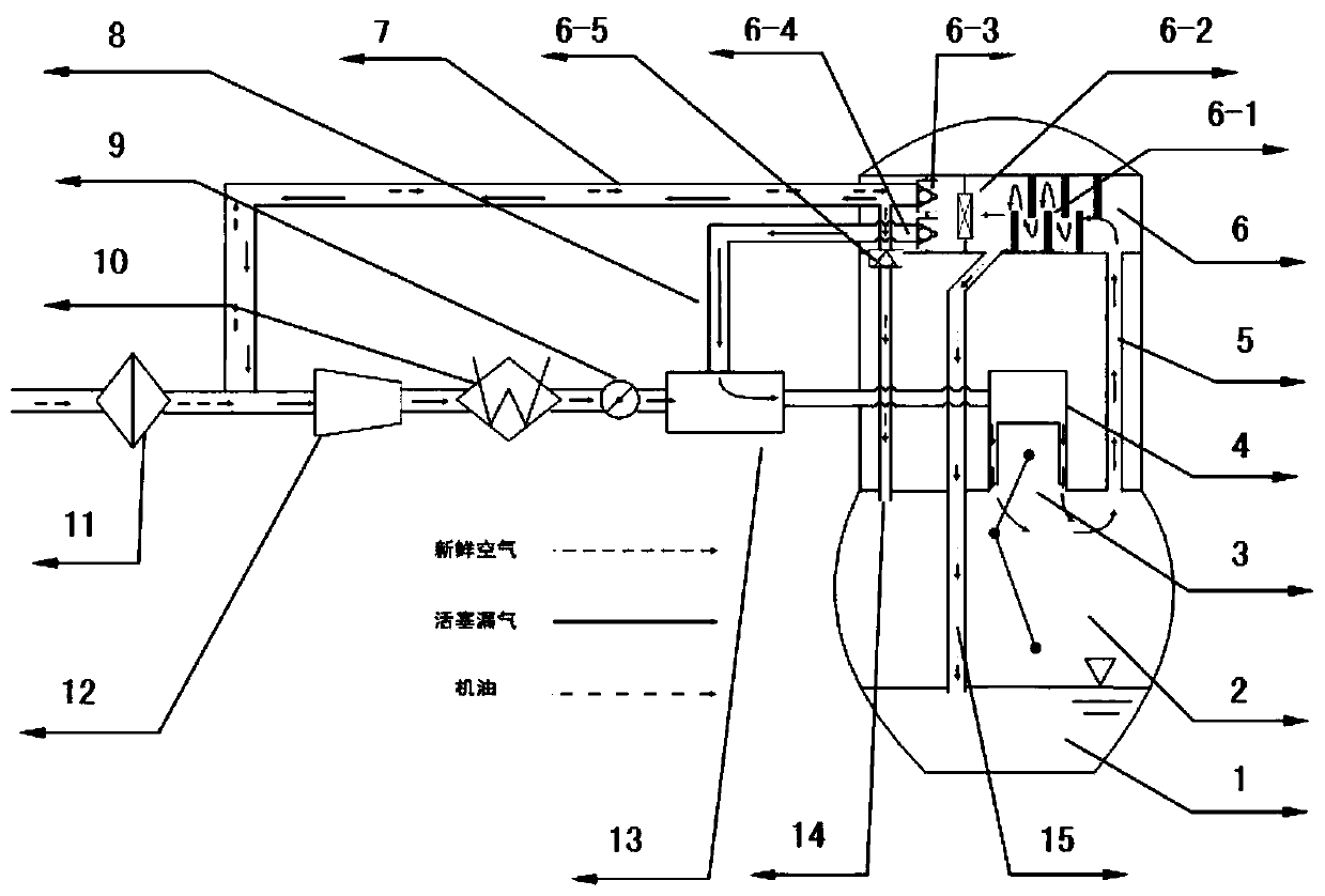
[0018] The present invention refers to figure 1 , a supercharged engine crankcase ventilation system structure includes oil pan 1, crankcase 2, piston assembly 3, cylinder barrel 4, intake passage 5, cylinder head cover 6, high-load crankcase ventilation pipe 7, low-load crankshaft Tank ventilation pipe 8, air filter 11, supercharger 12, intercooler 10, throttle valve 9, intake manifold 13, air supply passage 14 and oil return passage 15. The cylinder head cover 6 is integrated with an oil-gas separator 6-1, a PRV valve 6-2, a first one-way valve 6-3, a second one-way valve 6-4 and a third one-way valve 6-5.

[0019] The inlet of the oil return passage 15 is arranged between the oil-air separator 6-1 and the PRV valve 6-2, and th...


PUM


Abstract

The invention relates to a supercharged engine crank case ventilating system structure, and belongs to the technical field of vehicle engines. The structure comprises an oil bottom shell, a crank case, a piston assembly and a cylinder, wherein the piston assembly and the cylinder are arranged on the crank case. A cylinder head cover is communicated with one end of a high-load crank case ventilating pipe and one end of a low-load crank case ventilating pipe. The other end of the high-load crank case ventilating pipe is communicated with the output end of an air filter and communicated with theinput end of a supercharger. The other end of the low-load crank case ventilating pipe is communicated with the input end of an intake manifold. The output end of the intake manifold is communicated with the cylinder. The top of the crank case is communicated with one end of an air supplementation channel. The other end of the air supplementation channel is communicated with the high-load crank case ventilating pipe. The ventilation problem of a first check valve and a third check valve in a forward direction and a backward direction respectively is solved, redundant design is avoided, and meanwhile the reliability and durability of an engine are improved.

Description

technical field [0001] The invention relates to the technical field of automobile engines, in particular to a crankcase ventilation system structure of a supercharged engine. Background technique [0002] The unburned mixed gas and burned exhaust gas in the engine cylinder will enter the crankcase through the gap between the piston group and the cylinder, which is usually called piston blow-by. If the piston leakage cannot be discharged in time, the direct result is that the pressure in the crankcase will gradually increase, which will eventually force the oil dipstick or the crankshaft oil seal to come out, and the oil will leak. The fuel vapor, water vapor, especially the toxic and harmful by-products in the piston blow-by gas are directly discharged into the atmosphere, which will seriously pollute the environment and affect people's health. In order to solve the above problems, automotive engines usually design positive crankcase ventilation (Positive Crankcase Ventilat...

Claims


Application Information

Patent Timeline
Patent Type & Authority Patents(China)
IPC IPC(8): F01M13/00F01M13/04
CPCF01M13/0011F01M13/04F01M2013/0016F01M2013/0044F01M2013/0461
Inventor 崔燕平靳晓妍李聪龚婧瑶刘向晖刘成
Owner DONGFENG MOTOR CORP HUBEI
Learn More