Micro engine flame tube with internal and external hedging guide vane

A technology of guide vanes and flame tubes, which is applied in the field of micro-engines, can solve the problems of limited improvement of flame surface stability, poor stability, and small range of low-speed areas, etc., and achieve the effects of increased residence time, uniform mixing, and sufficient combustion

Inactive Publication Date: 2018-06-08
NORTHWESTERN POLYTECHNICAL UNIV
View PDF7 Cites 3 Cited by
  • Summary
  • Abstract
  • Description
  • Claims
  • Application Information

AI Technical Summary

Problems solved by technology

However, the range of the low-velocity zone produced by this method is small, the stability is poor, and the stability of the flame surface is limited.

Method used


Image

  • Micro engine flame tube with internal and external hedging guide vane
  • Micro engine flame tube with internal and external hedging guide vane
  • Micro engine flame tube with internal and external hedging guide vane

Examples


Embodiment Construction

[0020] The present invention will be further described now in conjunction with accompanying drawing:

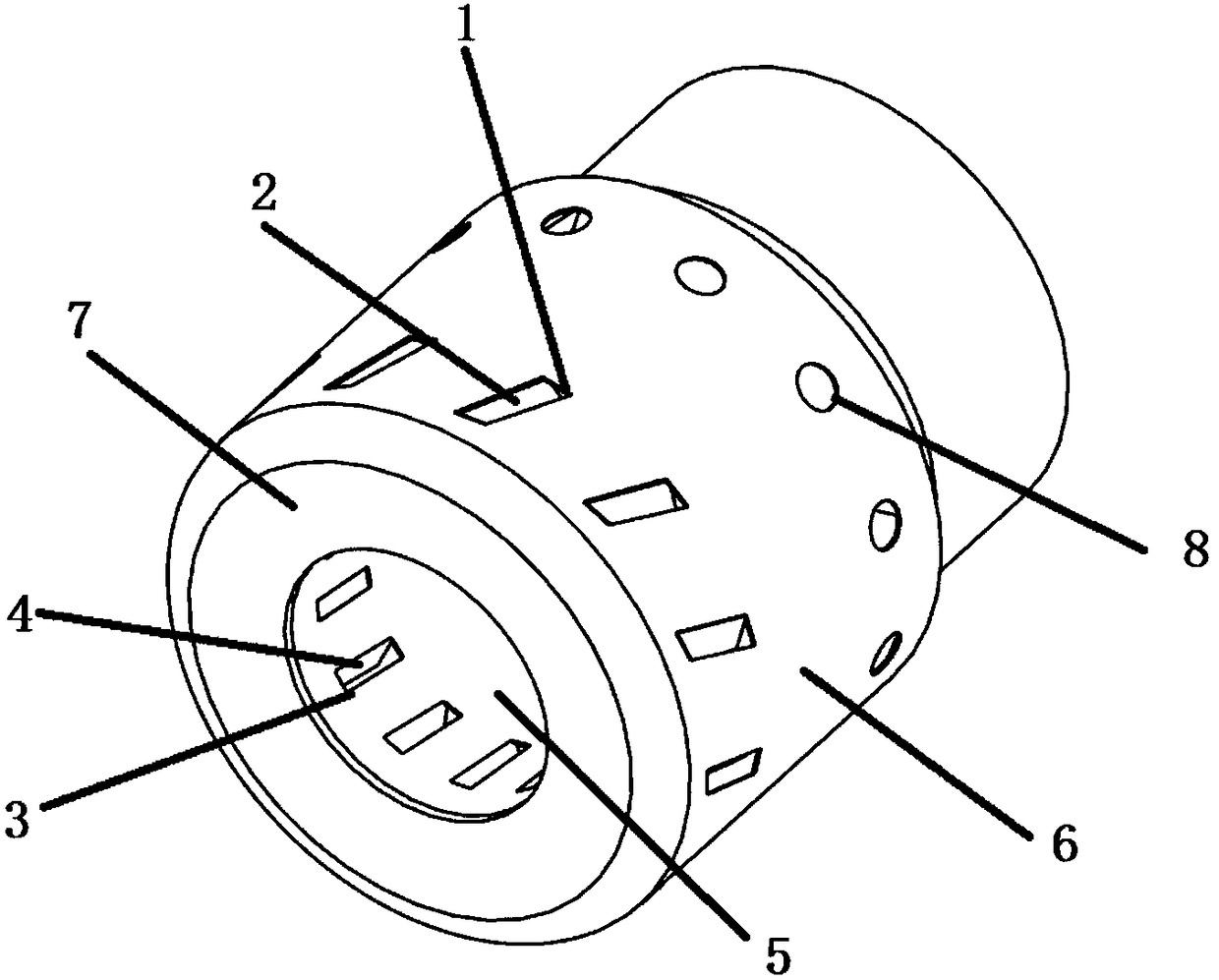
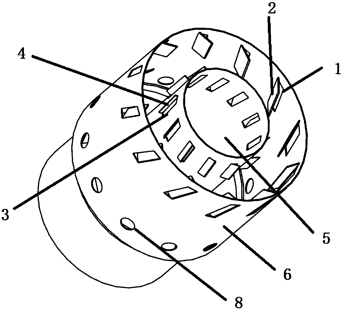
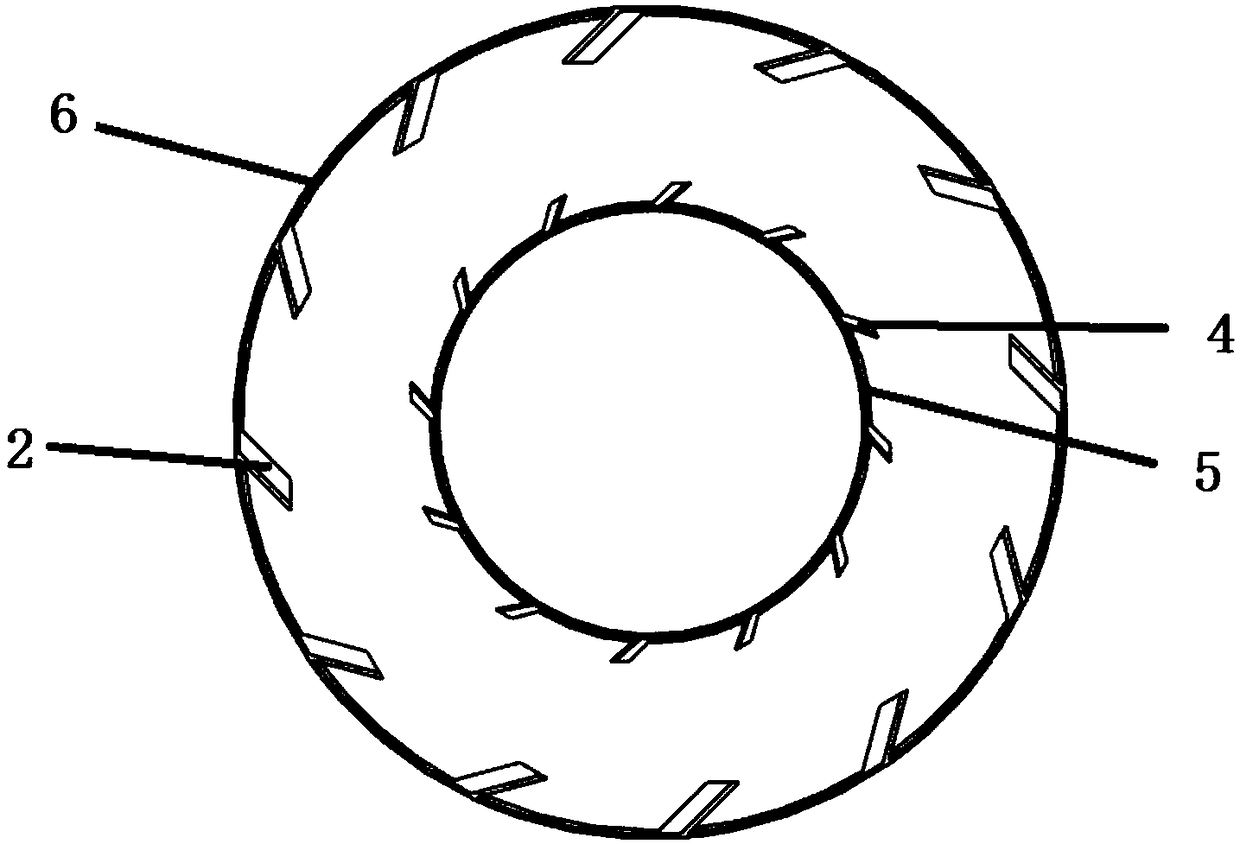
[0021] combine figure 1 , figure 2 , image 3 with Figure 4 , the invention provides a structural design scheme of a micro-engine flame tube with inner and outer opposing guide vanes. figure 1 It is a three-dimensional schematic diagram of a micro-engine flame tube with internal and external opposing guide vanes, figure 2 In order to remove the three-dimensional schematic diagram of the flame tube on the front face, image 3 It is a schematic diagram of the circumferential distribution of the inner and outer opposing guide vanes, Figure 4 It is a cross-sectional view of a micro-engine flame tube with inner and outer opposing guide vanes.

[0022] according to Figure 4 As shown, the present invention rationally designs the main combustion holes of the inner and outer casings of the flame tube and sets up inner and outer counterpoise guide vanes, so that the airflow...


PUM


Abstract

The invention provides a structural design scheme of a micro engine flame tube with internal and external hedging guide vanes. Compared with a traditional micro engine flame tube, by arranging the internal guide vanes and the external guide vanes on the portions, close to the front end of the flame tube, of an inner shell and an outer shell of the flame tube, airflow entering the flame tube from an external primary hole becomes rotating inward airflow with three kinds of component velocities in the axial direction, the tangent direction and the radial direction, the velocity of the airflow entering the flame tube from an internal primary hole adopts outwards rotating, and the internal airflow and the external airflow are encountered and subjected to hedging in the flame tube; on one hand,the airflow velocity is lowered to form a low velocity zone, the internal airflow structure of the flame tube is improved, and then stable combustion is achieved; on the other hand, the hedging area has very high scale of turbulence, fuel oil is sprayed into the area to be better mixed with air, and combustion is more thorough.

Description

technical field [0001] The invention belongs to the field of micro-engines, and in particular relates to a micro-engine flame tube with inner and outer opposing guide blades. Background technique [0002] A micro engine refers to an engine with a size of centimeter or millimeter. It has the advantages of small size, light weight, large output energy, and high density. As a future high energy storage density device, micro power system has become a research topic at home and abroad. Hotspots, micro-engines have also become one of the most promising power. In the small-scale power system program of the U.S. Department of Defense Advanced Research Projects Agency, it focuses on supporting research technologies related to micro-turbine engines with a thrust between 0.1 and 100N; Japan is developing a micro-turbine engine with a power of 100W; China Taiwan and domestic Nanjing The University of Aeronautics and Astronautics, Beijing Aeronautics and Astronautics and other units hav...

Claims


Application Information

Patent Timeline
Patent Type & Authority Applications(China)
IPC IPC(8): F23R3/52F23R3/58
CPCF23R3/52F23R3/58
Inventor 张群张鹏海涵王鑫宋亚恒寇睿李承钰
Owner NORTHWESTERN POLYTECHNICAL UNIV
Why Eureka
Try Eureka