Massive thermal shock testing device of hyperthermal material

A test device and thermal shock technology, which is applied in the direction of measuring devices, analysis materials, instruments, etc., can solve the problems of large dispersion of brittle materials, great influence of environmental factors, and impracticability of test pieces, so as to achieve accurate impact performance testing and environmental factors. Small influence, avoiding the effect of initial temperature

Active Publication Date: 2018-06-08
CHONGQING UNIV
View PDF7 Cites 14 Cited by
  • Summary
  • Abstract
  • Description
  • Claims
  • Application Information

AI Technical Summary

Problems solved by technology

[0005] 1. Only one test piece can be clamped in one experiment, the efficiency is low, and the accuracy of the experiment is not enough;
[0006] 2. The test piece can only switch between the environmental media at the speed of free fall, so that the influence of different initial velocities on the thermal shock of ceramic materials cannot be obtained
[0007] 3. The test piece cannot achieve a high and wide range of initial temperature, so as to study the influence of the initial temperature on the experimental results
[0008] 4. Due to the high environmental requirements of the thermal shock test, and the brittle materials are highly dispersed and greatly influenced by environmental factors, the consistency of the test conditions of the same batch of specimens cannot be guaranteed, including the initial temperature of the test, the target temperature, the ambient atmosphere, and the thermal shock history. time, sample switching speed, etc.
[0009] The above problems lead to large errors in the test process, resulting in the experimental results not being able to characterize the thermal shock resistance of ceramic materials, and the efficiency is low

Method used


Image

  • Massive thermal shock testing device of hyperthermal material
  • Massive thermal shock testing device of hyperthermal material
  • Massive thermal shock testing device of hyperthermal material

Examples


Embodiment Construction

[0024] Below in conjunction with accompanying drawing and embodiment the present invention will be further described:

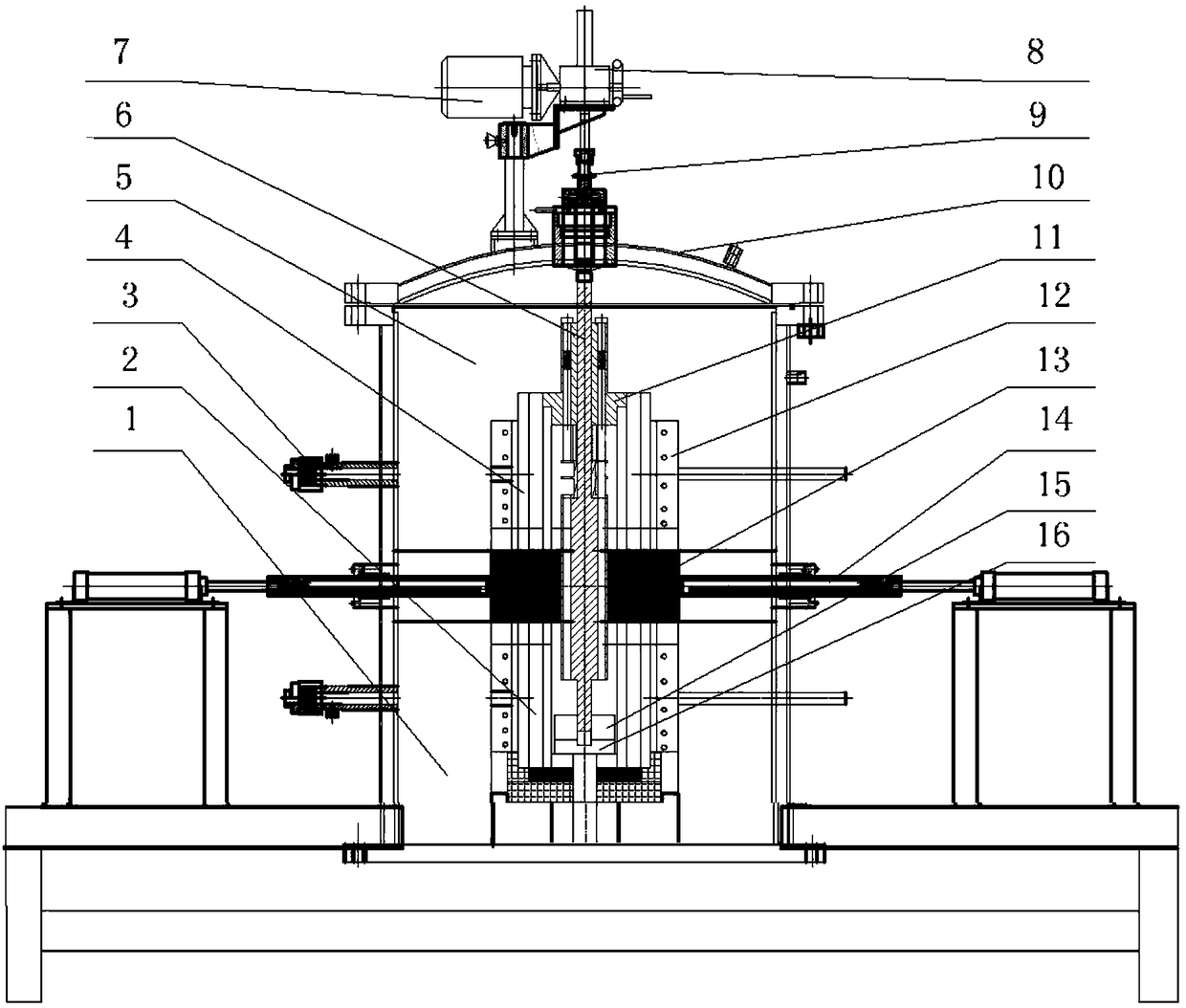
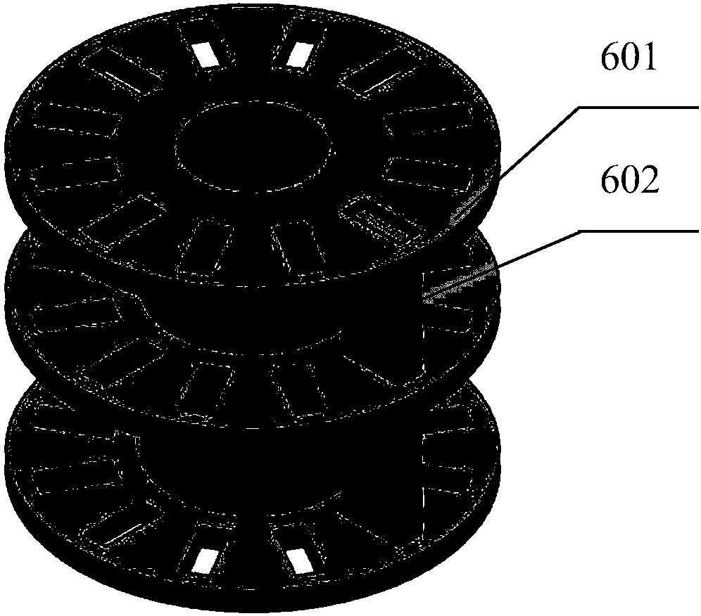
[0025] like figure 1 As shown, the present invention includes two upper environmental modules 5 and lower environmental modules 1 overlapping from top to bottom, each environmental module is provided with an upper heating furnace 4 and a lower heating furnace 2 correspondingly, and the upper environmental module 5 and the lower environmental module 1 The airtight partitions 13 controlled to open and close by the pneumatic push rod 14 are isolated; the top of the upper heating furnace 4 is equipped with a test piece preloading mechanism 11, which includes a fixing frame 114, and the inside of the fixing frame 114 is from top to bottom. Screws 111, springs 112 and push fingers 113 are respectively installed below. A test piece introduction mechanism 6 is installed between the upper heating furnace 4 and the lower heating furnace 2, the upper end of which is co...


PUM


Abstract

The invention discloses a massive thermal shock testing device of a hyperthermal material. The device comprises an upper environment module and a lower environment module, wherein upper heating furnaces and lower heating furnaces are correspondingly arranged in the environment modules; a sealing partition is arranged between the two environment modules; and a specimen prepressing mechanism is mounted at the top of the upper heating furnace and comprises a fixing frame, screws, springs and push fingers. A specimen introduction mechanism is mounted between the upper heating furnace and the lowerheating furnace in a penetrating manner; the upper end of the specimen introduction mechanism is connected with a speed reducer via a transmission shaft and then connected with a motor; the specimenintroduction mechanism is equipped with specimen retainers, specimens and a specimen guide pipe; and a cushion is mounted at the bottom of the specimen introduction mechanism and supported by a tray.The device has the technical effects that the device can ensure controllable initial speeds of the specimens to be tested, achieve testing of the specimens in the same lot at the different initial speeds and perform massive thermal shock resistance testing of the specimens, is high in efficiency, and can ensure thermal shock testing environments of the specimens in the same lot are good in consistency and testing results are high in reliability.

Description

technical field [0001] The invention relates to a thermal shock test device, in particular to a batch thermal shock test device for ultra-high temperature materials. Background technique [0002] Ultra-high temperature materials refer to the most heat-resistant advanced materials that can still be used as usual in harsh environments such as stress and oxidation, and at ultra-high temperatures of about 2000°C. [0003] Hypersonic vehicles are an important field for aerospace technology to explore new flight limits. It will greatly promote the realization of aerospace integration, and it is a hot field for the development of advanced aviation countries in recent years. The extreme environment of long-duration aircraft flight, atmospheric re-entry flight and trans-atmospheric flight has increasingly stringent requirements on the performance of structural materials. At present, the service temperature of traditional metal materials is close to its limit and cannot fully meet t...

Claims


Application Information

Patent Timeline
Patent Type & Authority Applications(China)
IPC IPC(8): G01N3/60G01N3/02G01N3/04
CPCG01N3/02G01N3/04G01N3/60G01N2203/0226
Inventor 李卫国王文玲彭方澜冯开翔麻建坐陶勇张先贺寇海波邵家兴邓勇李莹张续耀张欣徐念东董攀方岱宁
Owner CHONGQING UNIV
Why Eureka
Try Eureka