BRDF normalizing correction method for airborne push-broom hyperspectral image of forest region

A correction method and push-broom technology, applied in the field of forestry informatization, to achieve the effect of clear logic and strong adaptability

Active Publication Date: 2018-06-08
RES INST OF FOREST RESOURCE INFORMATION TECHN CHINESE ACADEMY OF FORESTRY
11 Cites 16 Cited by

AI-Extracted Technical Summary

Problems solved by technology

[0005] The purpose of the present invention is to solve the problem that the existing BRDF correction algorithm cannot be based on the imaging characteristics of the airborne push-broom hyperspectral equipment and the radiation correction in the complex imaging environment of the fore...

Abstract

The invention provides a BRDF (bidirectional reflectance distribution function) normalizing correction method for the airborne push-broom hyperspectral image of a forest region having an accidented relief. The method comprises the following steps: calculating the plane-based sun-observation geometry of the pixels of the image by using the observation view field and flight attitude information of an airborne push-broom hyperspectral device and the sun position at a data acquisition moment, extracting the slope and aspect information of the corresponding pixels based on high-precision DEM (digital elevation model) data, rotating the plane-based sun-observation geometry of the pixels to true sun-observation geometry, extracting the pixels of every surface feature from classified image data, forming a multi-angle observation reflectivity data set, and constructing a BRDF model according to the true sun-observation geometry; and normalizing the multi-angle direction reflectivity in the image to the reflectivity at an assigned observation-sun angle by adopting a multiplicative normalization factor. The method can effectively correct the BRDF effect of the airborne push-broom hyperspectral image of the forest region having the accidented relief, and is of great significance to the quantitative study of subsequent images.

Application Domain

Technology Topic

Image

  • BRDF normalizing correction method for airborne push-broom hyperspectral image of forest region
  • BRDF normalizing correction method for airborne push-broom hyperspectral image of forest region
  • BRDF normalizing correction method for airborne push-broom hyperspectral image of forest region

Examples

  • Experimental program(1)

Example Embodiment

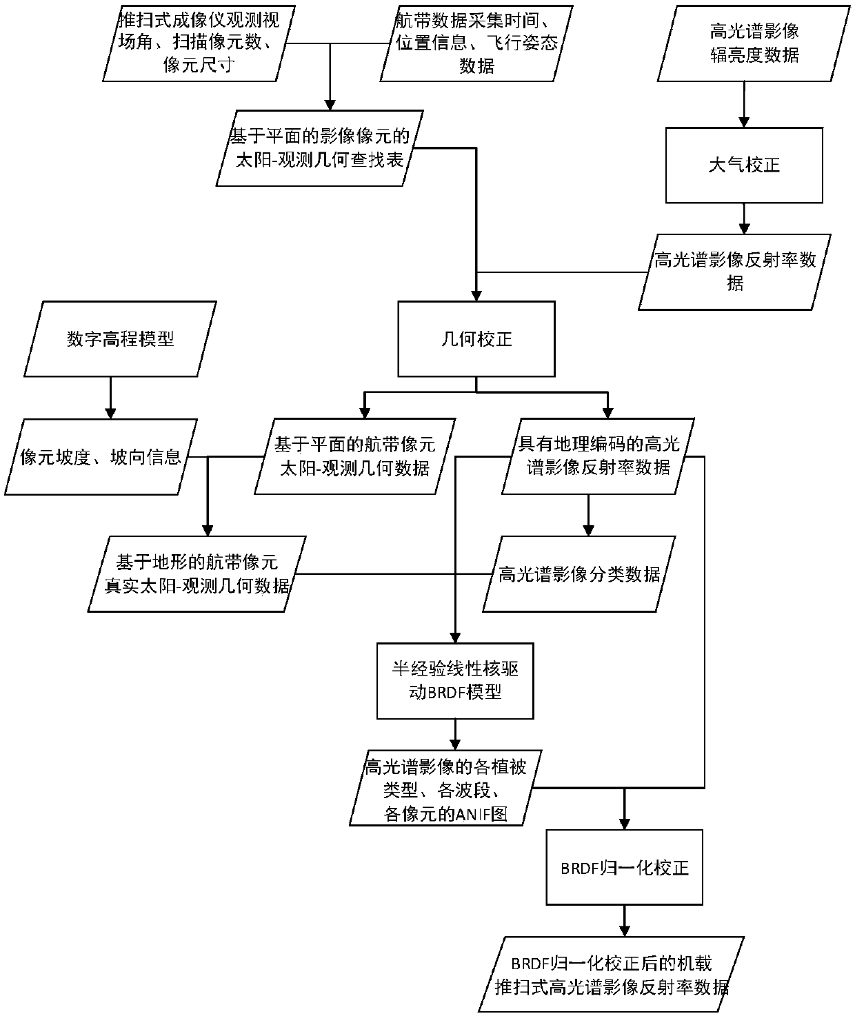
[0039] The following will clearly and completely describe the technical solutions in the embodiments of the present invention with reference to the accompanying drawings in the embodiments of the present invention. Obviously, the described embodiments are only some, not all, embodiments of the present invention. Based on the embodiments of the present invention, all other embodiments obtained by persons of ordinary skill in the art without making creative efforts belong to the protection scope of the present invention.
[0040] like figure 1 As shown, a binomial reflectance distribution function (BRDF) normalization correction method for airborne push-broom hyperspectral imagery in forested areas with undulating terrain, the specific implementation steps are as follows:
[0041] Step 1: Calculate the solar-observation geometry of the pixel
[0042] Relative to images, the solar zenith angle refers to the angle between the direct rays of the sun and the vertical line at the ground level. The solar azimuth refers to the orientation of the sun relative to the pixel, usually the north direction is 0°, and the east direction is 90°. The zenith angle and azimuth angle of the sun can be calculated using the geographical coordinates and the shooting time of the image. Since the airborne equipment usually collects images of a single flight belt within 10 to 20 minutes, the position of the sun does not change much, so the fixed solar zenith angle and azimuth angle corresponding to the center position of the image flight belt and the acquisition time of this position can be simplified as The geometric information of the sun corresponding to all the pixels of the air belt image. If the acquisition time of a single air strip image is too long, the solar geometric information corresponding to the image pixel can be calculated in sections according to the above method.
[0043] This example is based on the characteristics of the airborne AISA Eagle II scanning hyperspectral imaging sensor. During the sensor scanning process, each pixel of the original image has a unique observation zenith angle and observation azimuth angle. Calculate the observation zenith angle and observation azimuth angle for each pixel. According to the collinear equation of photogrammetry, if the origin position of the ground coordinate system is translated to the center position of the sensor scanning line, the transformation process from the coordinate system coordinates of the frame mark to the coordinate system coordinates of the ground space is as follows:
[0044]
[0045]
[0046] In formula (1), (x, y) and (x 0 ,y 0 ) are the pixel coordinates and the coordinates of the image principal point S in the frame coordinate system; the push-broom imaging sensor scans and images the ground surface line by line, so different pixels on the same line are in the image space coordinate system (y-y 0 ) coordinates are all 0. The number of pixels within the width range of the sensor scanning line is 1024, and the pixel size is 0.012mm, then the coordinates of the principal point of the image are The vertical distance from the photographic center of the sensor to the imaging image, that is, the focal length f=18.50mm. (x-x 0 ,y-y 0 ,-f) is the three-dimensional coordinates of the pixel in the image space coordinate system, which is expressed as ( 0, -18.5). (u, v, w) are the three-dimensional coordinates of the pixel in the ground space coordinate system.
[0047] (2) In the formula, ω and k are the deflection angle, inclination angle and rotation angle respectively, which determine the direction of the three axes of the image space coordinate system in the ground coordinate system. The above information is provided by the airborne POS data, and the heading azimuth is α az. Observation zenith angle θ of pixel v with azimuth The calculation formula is as follows:
[0048]
[0049]
[0050] Step 2: Data Preparation
[0051] (1) Hyperspectral image geometric correction and atmospheric correction: according to step 1, construct the sun-observation geometry lookup table image data corresponding to each pixel of the original image row and column number. Simultaneous geometric correction of raw hyperspectral imagery and lookup table data. The original row and column number of the hyperspectral image after geometric correction will be rearranged according to the track information in the POS data and the high-resolution DEM data, but the look-up table data after geometric correction can still correspond to the solar-observation geometric information to the geometric A cell in the corrected hyperspectral imagery.
[0052] According to the airborne calibration parameter file, perform radiometric calibration on the geometrically corrected hyperspectral image above, and use ATCOR4 airborne atmospheric correction software or model (for image atmospheric correction, and finally obtain the geometrically corrected and atmospherically corrected ground object reflectance Hyperspectral image data.
[0053] (2) Slope and aspect information of the pixel: the slope α and aspect β information of the pixel are calculated by using the high-resolution DEM data within the coverage area of ​​the above-mentioned air belt image. The calculated slope and aspect images are spatially resampled to obtain the same spatial resolution as hyperspectral images.
[0054] (3) Classification of ground object types: According to the characteristics of forest area images, the above-mentioned ground object reflectance hyperspectral image data is used to classify ground objects, which are mainly divided into: coniferous forest, broad-leaved forest, grassland, bare soil, water body, road, Buildings, etc., among which coniferous forest and broad-leaved forest can be further subdivided into tree species. In this way, the object classification map within the image range of the air strip is obtained.
[0055] Step 3: Calculate the real sun-observation geometry of the pixel
[0056] The solar-observational geometry of the cells described in Step 1 is only for areas where the image coverage is flat terrain. For forest areas with undulating topography, due to the difference in slope and aspect angle corresponding to each pixel, its solar-observation geometry also changes accordingly. In order to obtain the real solar-observation geometry of the pixel, it is necessary to convert the pixel based on the earth plane coordinate system (global coordinate system) to the corresponding slope of the pixel according to its corresponding slope (α) and slope direction (β) information in the local coordinate system. Using the coordinates of the sun and the sensor in the local coordinate system of the pixel, the real solar incidence and observation geometry of the slope corresponding to the pixel can be calculated. The conversion method from the global coordinate system to the local coordinate system includes: first, rotate the global coordinate system around the w-axis (π/2-β), and then rotate the rotated coordinate system around the v-axis by α to obtain the local coordinates based on the slope Tie. Assuming that (x′, y′, z′) is a new coordinate transformation that transforms the position (u′, v′, w′) of the sensor in the global coordinate system into the local coordinate system through coordinate system transformation, the transformation formula can be Expressed as:
[0057]
[0058] Among them, r is the straight-line distance from the sensor to the pixel, which will be ignored as a common item in the subsequent angle calculation, and r can also be regarded as a unit distance 1 and brought into the formula (5) for calculation.
[0059] In the local coordinate system, the real observed zenith angle θ′ of the pixel v and azimuth Calculated by formulas (6) and (7) respectively:
[0060]
[0061]
[0062] Similarly, the real solar zenith angle and azimuth angle of the slope pixel can also be calculated by the above method.
[0063] Step 4: Extract BRDF characteristics of ground objects
[0064] (1) BRDF model
[0065] Hyperspectral imagery can be viewed as a novel multi-angle observational dataset based on the true solar-observation geometry of the cells. Under the assumption that the image range area has a uniform forest structure and surface object structure, and does not change with slope and slope aspect, the present invention adopts a semi-empirical linear kernel-driven binomial reflection model for the BRDF effect of different tree species on the new multi-angle data set Simulations were performed with a combination of volume scattering Ross-Thick kernels and geometric optics Li-Sparse kernels. The specific calculation formula of BRDF model and kernel is as follows:
[0066]
[0067] in is the binomial reflectance distribution function, which is the solar zenith angle θ′ s , the observed zenith angle θ′ v , the relative azimuth of the sun and the sensor Function of different object types c and wavelength λ;
[0068] K vol and K geo Represent the volume scattering Ross-Thick kernel and the geometric optics Li-Sparse kernel respectively, and the calculation process is as follows:
[0069]
[0070]
[0071]
[0072]
[0073]
[0074]
[0075]
[0076]
[0077]
[0078] According to the MODIS BRDF/Albedo product algorithm parameters, the present invention sets the f iso (c, λ), f vol (c,λ) and f geo Respectively represent the coefficients corresponding to each kernel function item in the BRDF model of the reflectivity of a certain surface object type in a certain band.
[0079] (2) BRDF model kernel parameter solution
[0080] Due to the high spatial resolution of the airborne push-broom hyperspectral images, a single single-band flight belt image usually contains tens of millions to hundreds of millions of pixels. In order to quickly and relatively accurately solve the BRDF model parameters, the present invention is based on The slope and aspect information is stratified sampling for the new multi-angle observation data set to obtain m (m is a positive integer) pixel subsets, and then extract n (n is a positive integer) the reflectance values ​​of each band of the pixels and the solar-observation geometric data of the local coordinate system, and use the least square method to solve the BRDF model parameters of the single-band reflectance of the ground object. The modeling process is as follows Formula (18 shows.
[0081]
[0082]
[0083] Solve X·B=Y, then X T ·X·B=X T ·Y, the obtainable B=(X T X) -1 x T Y, that is, the coefficient f corresponding to each kernel function item in the BRDF model of the reflectance of a certain surface object type in a certain band iso , f vol and f geo.
[0084] Step 5: Hyperspectral image BRDF correction
[0085] Calculate the Anisotropy Factor (ANIF) parameters of each pixel in each band of the hyperspectral image of the entire airway, and generate the ANIF map corresponding to the image. ANIF can reflect the relationship between the reflectivity in any direction of a certain band and the reflectivity in a specified direction, and its expression is as follows:
[0086]
[0087] is the fitted reflectance of a surface object under any sun-observation condition in a certain band, is the fixed solar zenith angle of a certain feature in a certain band observation zenith angle and the sun-sensor relative azimuth The fitting reflectivity under the condition of , usually choose the nadir direction observation, that is,
[0088] Use the above ANIF parameters to perform BRDF normalization correction on the hyperspectral image. The correction method is:
[0089]
[0090] Among them, ρ BRDF_Cor is the hyperspectral reflectance image corrected by BRDF normalization, ρ image is the ground object reflectance hyperspectral image data after geometric correction and atmospheric correction in step 2.
[0091] Finally, the accuracy of the algorithm is verified by visually comparing images and comparing the reflectivity of ground objects.
[0092] The following 1 takes Simao pine as an example to illustrate the case.
[0093] Implemented on a workstation computer equipped with Intel(R) Xeon(R) 1.70GHz dual-core processor and 32GB memory, taking the airborne push-broom AISA Eagle II hyperspectral image data in the undulating terrain forest area of ​​Yunnan as an example , adopt the method of the present invention, carry out BRDF normalization correction to image data ( figure 1 ). Compared with the observation geometry of the pixel without adding terrain factors ( Figure 2a , Figure 2c ) and the true observation geometry of the pixel ( Figure 2b , Figure 2d ), it can be seen that the real observation geometry of the pixel combined with terrain factors contains richer multi-angle observation information of ground objects, and avoids the BRDF shape caused by the unconstrained BRDF kernel-driven model inversion due to sparse multi-angle observations The problem of drastic change. Figure 3a , Figure 3b The BRDF shape representing the reflectance of typical vegetation types in the image in the red band and near-infrared band, it can be seen that the inversion result is reasonable. When the solar zenith angle is 30°, the ground objects show higher reflectivity in the direction of the hot spot . Figure 4a , Figure 4b It reflects that the BRDF normalized and corrected image can eliminate the influence of terrain factors on the vegetation reflectance to a certain extent compared with the original reflectance image. Figure 4c , Figure 4d Local detail shows that the same vegetation type in the image exhibits similar spectral reflectance properties. Depend on Figure 5b It can be obtained that in the image after BRDF normalization and correction, Simao pine on the shady and sunny slopes showed similar spectral reflectance characteristics, which improved the difference in vegetation spectral reflectance caused by terrain factors and airborne push-broom sensor observations ( Figure 5a ).
[0094] In the above-mentioned embodiment, first, according to the characteristics of the airborne push-broom hyperspectral imager, the plane-based sun-observation geometry is calculated for each pixel in the image; then the slope and aspect information corresponding to the pixel is obtained according to the DEM data, and the The solar-observation geometry of the pixel is transformed from the global coordinate system to the local coordinate system, that is, the solar-observation geometry of the pixel on the plane is rotated to the slope according to the slope and aspect of the pixel, so that each pixel can be obtained The real sun-observation geometry is used to construct a new multi-angle data set; the semi-empirical kernel-driven model is used to fit the new multi-angle data set to extract the BRDF characteristics of different tree species in the visible light to near-infrared band; finally, the multiplicative normalization factor is used to convert The directional reflectance at multiple angles for each cell in the image is normalized to the reflectance at a specified observation-sun angle. The invention can effectively correct the BRDF effect of the airborne push-broom hyperspectral image in the undulating terrain, and has great significance for the quantitative research of the follow-up image.
[0095] The above description is only illustrative of the present invention, rather than restrictive. Those of ordinary skill in the art understand that many modifications, changes, or Equivalent, but all will fall within the protection scope of the present invention.

PUM

no PUM

Description & Claims & Application Information

We can also present the details of the Description, Claims and Application information to help users get a comprehensive understanding of the technical details of the patent, such as background art, summary of invention, brief description of drawings, description of embodiments, and other original content. On the other hand, users can also determine the specific scope of protection of the technology through the list of claims; as well as understand the changes in the life cycle of the technology with the presentation of the patent timeline. Login to view more.

Similar technology patents

Classification and recommendation of technical efficacy words

  • Adaptable
  • Clear logic

Application interface rendering method and apparatus

ActiveCN105354013AAdaptableAvoid various pitfallsSpecific program execution arrangementsInformation mappingComputer graphics (images)
Owner:ALIBABA GRP HLDG LTD

Method for monitoring sleep respiration based on snore signals

InactiveCN104688229AClear logicCost controlRespiratory organ evaluationSensorsMonitor sleepEmergency medicine
Owner:PLA UNIV OF SCI & TECH +2
Why Eureka
Try Eureka