Laser radar system

A laser radar and laser pulse technology, applied in the field of environmental perception, can solve the problems of deviation from the receiving field of view, increase the difficulty of maintenance, and fail to give correction results, etc., and achieve the effect of high-precision scanning

Inactive Publication Date: 2018-06-08
HESAI TECH CO LTD
View PDF8 Cites 57 Cited by
  • Summary
  • Abstract
  • Description
  • Claims
  • Application Information

AI Technical Summary

Problems solved by technology

Once the directivity of the emitted beam changes, not only the lidar overlap factor correction curve becomes uncertain, but also the correct correction result cannot be given in the overlap area. When the pointing deviation is serious, it will deviate from the receiving field of view, resulting in the lidar being unable to detect obstacles thing
[0004] In the existing laser radar system, due to the deviation of the reflector, the working environment temperature of the semiconductor laser, the vibration of the platform, the replacement of the wavelength, the service life of the semiconductor laser itself, etc., it is difficult for the non-coaxial laser radar system to guarantee the emission. The beam is always coaxial or parallel to the optical axis of the receiving telescope
In addition, the existing laser radar system uses the rotation of the one-dimensional galvanometer to realize spatial scanning, which cannot meet the requirements of the laser radar for the scanning field of view, and the rotation of the galvanometer is controlled by the mechanical structure, which not only increases the difficulty of maintenance, but also limits the measurement precision

Method used


Image

  • Laser radar system
  • Laser radar system
  • Laser radar system

Examples


Embodiment Construction

[0024] In the existing laser radar system, due to the deviation of the reflector, the working environment temperature of the semiconductor laser, the vibration of the platform, the replacement of the wavelength, the service life of the semiconductor laser itself, etc., it is difficult for the non-coaxial laser radar system to guarantee the emission. The beam is always coaxial or parallel to the optical axis of the receiving telescope. In addition, the existing laser radar system uses the rotation of the one-dimensional galvanometer to realize spatial scanning, which cannot meet the requirements of the laser radar for the scanning field of view, and the rotation of the galvanometer is controlled by the mechanical structure, which not only increases the difficulty of maintenance, but also limits the measurement precision.

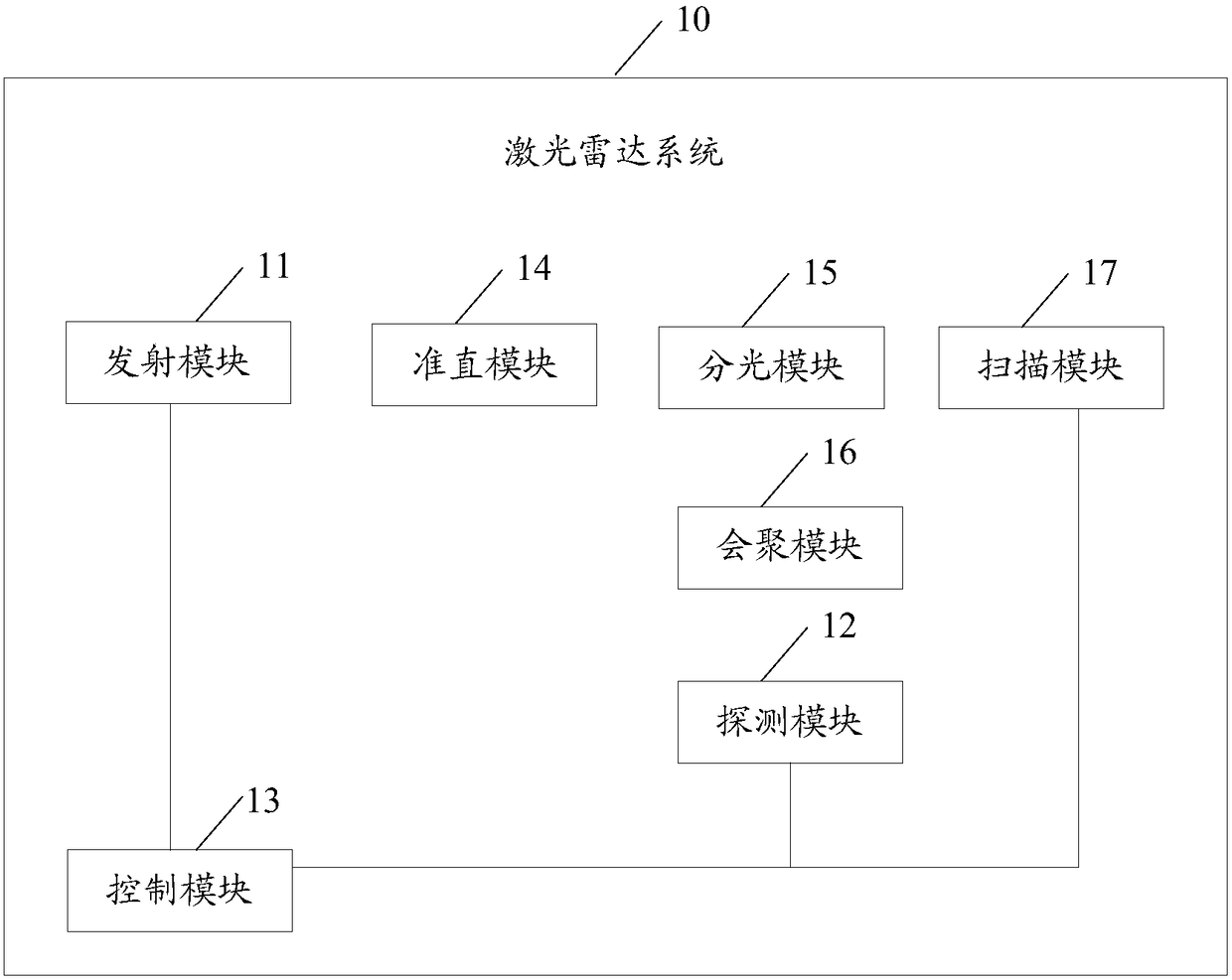
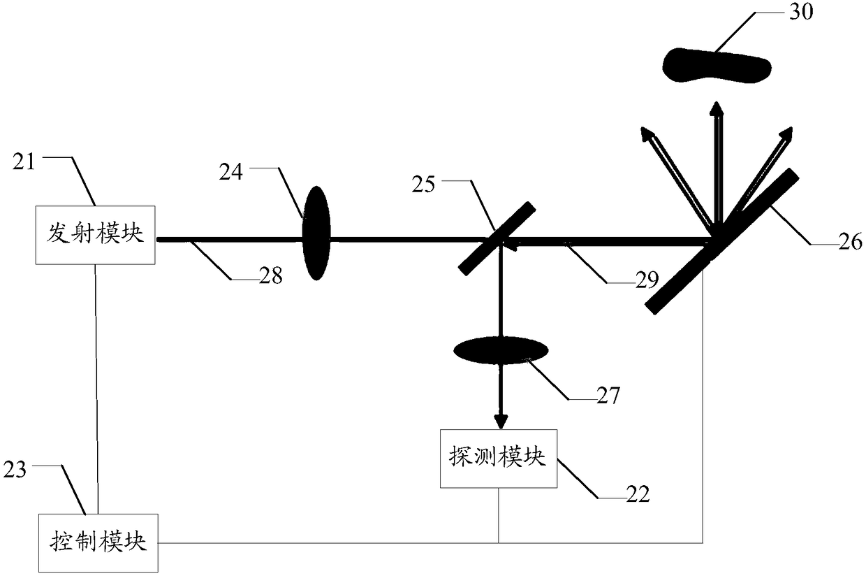
[0025] The embodiment of the present invention proposes a laser radar system. By setting the transmitting module, the collimating module, the beam splitting ...


PUM


Abstract

A laser radar system comprises an emission module, a detection module, a control module, a collimation module, a convergence module, a splitting module and a scanning module. The control module is coupled to the emission module, the detection module and the scanning module, and controls the emission module to generate and emit laser pulses, the scanning module to swing and the detection module toreflection signals of the laser pulses; the emission module, the collimation module, the splitting module and the scanning module are positioned in the same axis; the collimating module adjusts the laser pulses into parallel laser pulses; the splitting module is suitable for reflection signals of semi-transmitting laser pulses and semi-reflecting laser pulses; and the convergence module is suitable for convergence of reflection signals of the laser pulses. Via the system, it can be ensured that an emission optical path is coaxial with a reception optical path, and a 2D space is scanned in highprecision.

Description

technical field [0001] Embodiments of the present invention relate to the technical field of environment perception, and in particular to a laser radar system. Background technique [0002] Since it can detect whether there is an obstacle in front of driving and provide the distance information of the obstacle, the lidar system is widely used in various fields such as automatic driving. According to whether the optical axes of the transmitting optical path and the receiving optical path coincide, lidar can be divided into non-coaxial system and coaxial system. [0003] For any lidar system, in order to ensure that the emitted laser pulses enter the receiving field of view of the lidar after passing through the lidar blind zone and transition zone, the emitted laser pulses are required to be parallel to the optical axis of the receiving telescope. Once the directivity of the emitted beam changes, not only the lidar overlap factor correction curve becomes uncertain, but also ...

Claims


Application Information

Patent Timeline
Patent Type & Authority Applications(China)
IPC IPC(8): G01S17/93G01S17/10G01S7/481
CPCG01S7/481G01S7/4817G01S17/10G01S17/93G01S17/42G01S7/4812G02B27/283G02B26/101G01S17/06G02B5/20G02B26/10G02B27/30
Inventor 吴世祥叶良琛王瑞向少卿李一帆
Owner HESAI TECH CO LTD
Why Eureka
Try Eureka