
Super-resolution imaging system

A super-resolution imaging and astigmatism technology, applied in optical components, instruments, optics, etc., can solve problems such as limiting applications, reducing the imaging depth and spatial resolution of STED super-resolution imaging systems, and affecting imaging quality.

Active Publication Date: 2018-06-08
SHENZHEN UNIV
View PDF5 Cites 9 Cited by
  • Summary
  • Abstract
  • Description
  • Claims
  • Application Information

AI Technical Summary

Problems solved by technology

[0004] The main purpose of the present invention is to provide a super-resolution imaging system, which aims to solve the problems existing in the existing STED super-resolution imaging system due to the inclusion of many optical elements, the surface unevenness of biological samples, and the non-uniformity of the internal refractive index distribution. Characteristics and other factors will bring aberrations to the STED super-resolution imaging system, reduce the imaging depth and spatial resolution of the STED super-resolution imaging system, affect the imaging quality, and limit its technical problems in biomedical applications

Method used


Image

  • Super-resolution imaging system
  • Super-resolution imaging system
  • Super-resolution imaging system

Examples


Embodiment Construction

[0057] In order to make the purpose, features and advantages of the present invention more obvious and understandable, the technical solutions in the embodiments of the present invention will be clearly and completely described below in conjunction with the accompanying drawings in the embodiments of the present invention. Obviously, the described The embodiments are only some of the embodiments of the present invention, but not all of them. Based on the embodiments of the present invention, all other embodiments obtained by those skilled in the art without making creative efforts belong to the protection scope of the present invention.

[0058] In order to illustrate the technical solutions of the present invention, specific examples are used below to illustrate.

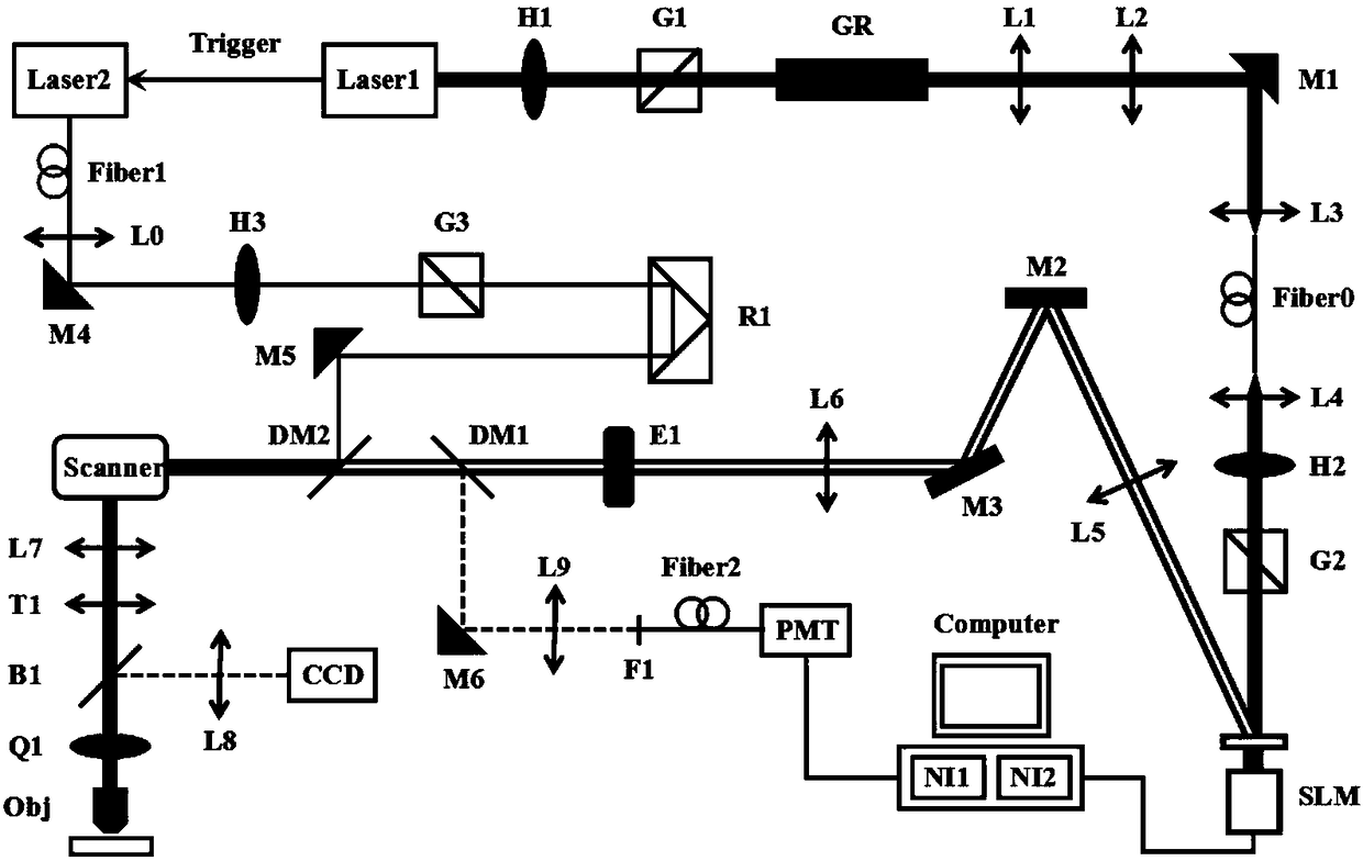
[0059] see figure 1 , figure 1 A schematic structural diagram of a super-resolution imaging system provided in the first embodiment of the present invention, including: a femtosecond laser Laser1, used to generat...


PUM


Abstract

The invention discloses a super-resolution imaging system comprising a femtosecond laser, a picosecond laser, a first data acquisition card, a second data acquisition card and a spatial light modulator. The dissipation light generated by the femtosecond laser and the exciting light generated by the picosecond laser are emitted to a sample and then a fluorescence signal is generated. The second data acquisition card converts the fluorescence signal into voltage information. The voltage information acts as the fitness value of a genetic algorithm. The voltage information is calculated accordingto the genetic algorithm and a maximum voltage absolute value is obtained, and a phase diagram corresponding to the maximum voltage absolute value acts as a phase compensation diagram. The phase compensation diagram is superposed on the dissipation light to perform aberration correction on the dissipation light so that the aberration introduced in the STED imaging process can be overcome, the imaging depth and the spatial resolution of the STED super-resolution imaging system can be enhanced and thus the super-resolution imaging system can be widely applied in physical medicine and other fields.

Description

technical field [0001] The invention relates to the field of optical microscopic imaging, in particular to a super-resolution imaging system. Background technique [0002] In the optical system, if all the rays emitted from the object point are focused on one point through the STED super-resolution imaging system, then this point is called the perfect image of the object point. If the object point is in the vertical When moving on the plane, its perfect image also moves linearly on the vertical plane. This STED super-resolution imaging system is an ideal STED super-resolution imaging system. However, STED super-resolution imaging systems usually contain many optical components, such as many lenses, glass slides, dichroic mirrors and mirrors, and artificially built STED super-resolution imaging systems cannot achieve precise control of light. At the same time, biological samples have the characteristics of surface unevenness and internal refractive index distribution. These ...

Claims


Application Information

Patent Timeline
Patent Type & Authority Applications(China)
IPC IPC(8): G02B27/58
CPCG02B27/58
Inventor 严伟屈军乐王璐玮叶彤
Owner SHENZHEN UNIV
Learn More