
Stator iron core of brushless motor and brushless motor

A stator core and brushless motor technology, applied in the direction of electrical components, electromechanical devices, electric components, etc., can solve the problems of large stator and inconvenient positioning of the stator, so as to avoid circular rotation, ensure long-term low-noise operation, and facilitate The effect of installation positioning

Pending Publication Date: 2018-06-08
SUZHOU CLEAN BLOOM ELECTRIC CO LTD
View PDF5 Cites 1 Cited by
  • Summary
  • Abstract
  • Description
  • Claims
  • Application Information

AI Technical Summary

Problems solved by technology

[0002] At present, brushless motors are mostly used in small motors for household appliances on the market. The main research direction of this type of brushless motors is miniaturization and quietness. At present, they have formed a general design method and finalized products. However, due to the iron core, one of the core components There is still room for further design optimization. In addition, there is room for further improvement in the design of the shape of each component and the connection structure in the overall structure. For example, most of the small brushless motors on the market now have the following defects: the overall size is too large, and the commutation performance is still low. Can be optimized, the stator size is too large, and the positioning of the stator is not very convenient

Method used


Image

  • Stator iron core of brushless motor and brushless motor
  • Stator iron core of brushless motor and brushless motor
  • Stator iron core of brushless motor and brushless motor

Examples


Embodiment Construction

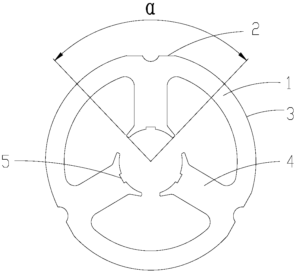
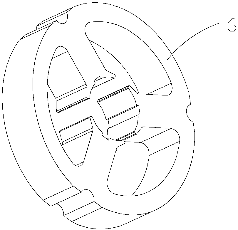
[0030] The present invention provides a brushless motor stator core, which includes an annular yoke 1 and a plurality of teeth 4 extending toward the axis of the yoke 1, and the plurality of teeth 4 are uniform along the inner circle of the yoke 1 The distribution also includes the positioning side 2 on the outer ring of the yoke 1, the positioning side 2 is a straight side, the adjacent side of the positioning side 2 on the yoke 1 is an arc-shaped side 3, and the arc-shaped side 3 forms a pole shoe, and the pole shoe angle The range α is 80°‐89.5°.

[0031] The beneficial effects are: the present invention can realize a smaller size design by providing a positioning edge on the outer ring of the yoke, and the positioning edge is a straight edge, and the adjacent edge of the positioning edge is an arc edge. The combined positioning of the shape edge achieves more accurate positioning, and the commutation performance of the brushless motor is improved by setting the pole shoe a...


PUM


Abstract

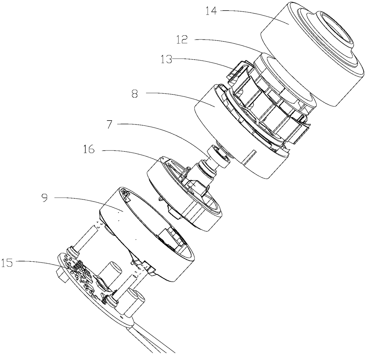
Provided in the invention is a stator iron core of a brushless motor. The stator iron core comprises an annular yoke portion and a plurality of teeth extending on the yoke portion towards an axis. A straight-edge positioning edge is arranged on the outer ring of the yoke portion; an arc edge is adjacent to the positioning edge on the yoke portion; and the angular range of a pole shoe is from 80 degrees to 89.5 degrees. Besides, the invention also provides a motor being composed of a stator iron core, a rotor passing through the center of the stator iron core, a first bracket for fixing end portions of the stator iron core and the rotor, a circuit board fixedly connected to the first bracket, a second bracket connected fixedly and cooperatively with the first bracket. The contours of the innermost sides of the inner walls of the first bracket and the second bracket are consistent with the external contour of the stator and outer straight edges and outer positioning edges are formed. Inaddition, the motor also includes an iron core bracket coating the stator iron core, a moving impeller fixedly connected with the rotor, and an annular fixed impeller coating the moving impeller; thefixed impeller is fixedly connected to the inside of a cover case fixedly connected with the second bracket; and a circuit board is fixedly connected to the first bracket. The stator iron core that can be installed and located conveniently has the good commutation performance within a limited size and a smaller size.

Description

technical field [0001] The invention relates to a stator iron core of a brushless motor and the brushless motor. Background technique [0002] At present, most of the small motors for household appliances in the market use brushless motors. The main research direction of this type of brushless motors is miniaturization and quietness. At present, they have formed a general design method and finalized products. However, due to the iron core, one of the core components There is still room for further design optimization. In addition, there is room for further improvement in the design of the shape of each component and the connection structure in the overall structure. It can be optimized, the stator size is too large, and the positioning of the stator is not very convenient. Contents of the invention [0003] In order to solve the above technical problems, the present invention provides a brushless motor stator core, which includes an annular yoke and a plurality of teeth e...

Claims


Application Information

Patent Timeline
Patent Type & Authority Applications(China)
IPC IPC(8): H02K1/14H02K1/18
CPCH02K1/146H02K1/185H02K2213/03
Inventor 潘景良
Owner SUZHOU CLEAN BLOOM ELECTRIC CO LTD
Learn More