Interface circuit

A technology of interface circuit and clamping circuit, applied in the direction of logic circuit, logic circuit connection/interface layout, electrical components, etc., can solve the problem of limiting the scope of application of input circuit and output circuit

Active Publication Date: 2018-06-08
SHANGHAI FUDAN MICROELECTRONICS GROUP
View PDF9 Cites 5 Cited by
  • Summary
  • Abstract
  • Description
  • Claims
  • Application Information

AI Technical Summary

Problems solved by technology

[0003] However, the existing input circuit is limited by the withstand voltage condition of the port device, so that the input circ...

Method used


Image

  • Interface circuit
  • Interface circuit
  • Interface circuit

Examples


Embodiment Construction

[0038] In the prior art, the port power supply voltage V of the input circuit and the output circuit in the input and output circuit CCO Although it can be changed according to different port level standards, it is limited by the withstand voltage value of the port device, so that the port power supply voltage V of the input and output circuits CCO or less than or equal to the auxiliary supply V AUX , so that the output voltage of the PAD terminal of the input-output circuit can only swing within a small voltage range.

[0039] For example, when a digital logic level signal V INT 0.9V, the auxiliary supply V AUX is 1.8V, and the withstand voltage of the I / O device is also 1.8V, then the port power supply voltage V CCO Only the level standard less than or equal to 1.8V can be selected, and the level standards of 2.5V and 3.3V that are commonly used are not compatible.

[0040] In order to solve the above-mentioned problems existing in the prior art, the technical solution a...


PUM


Abstract

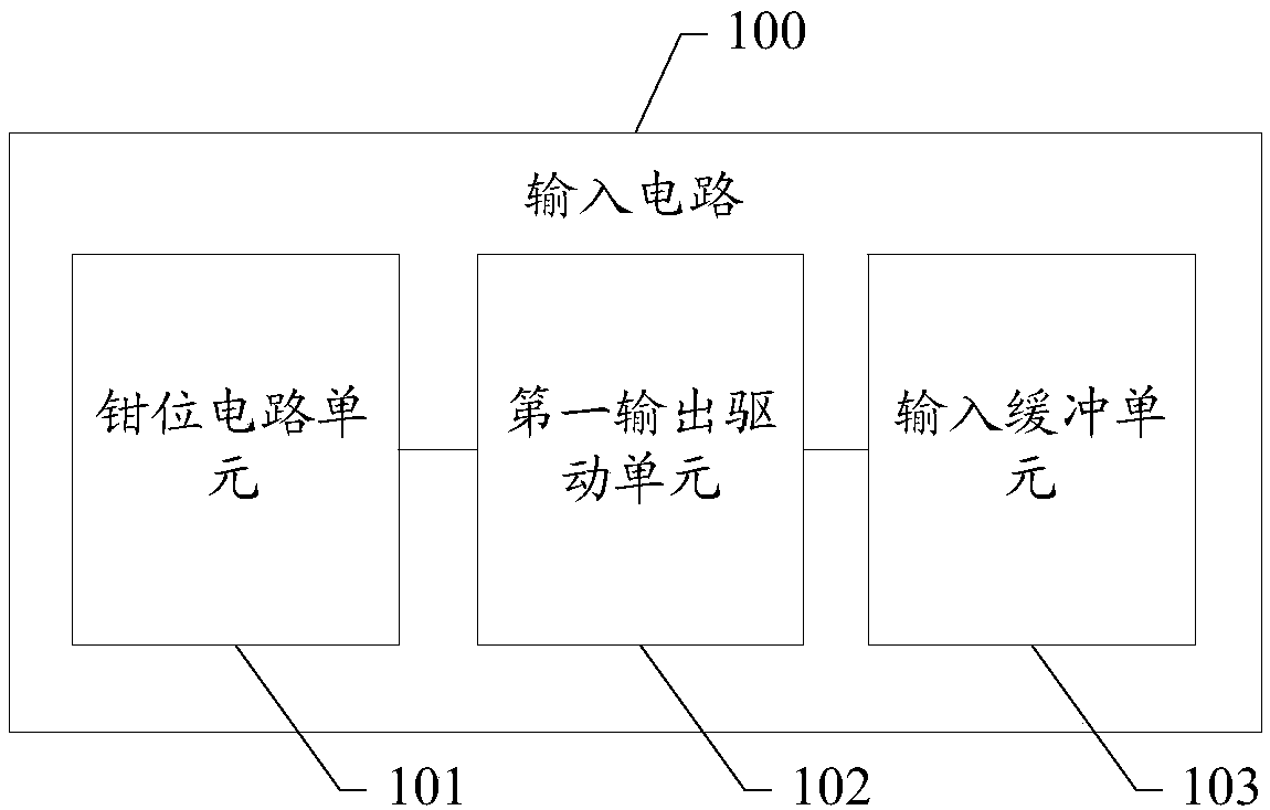
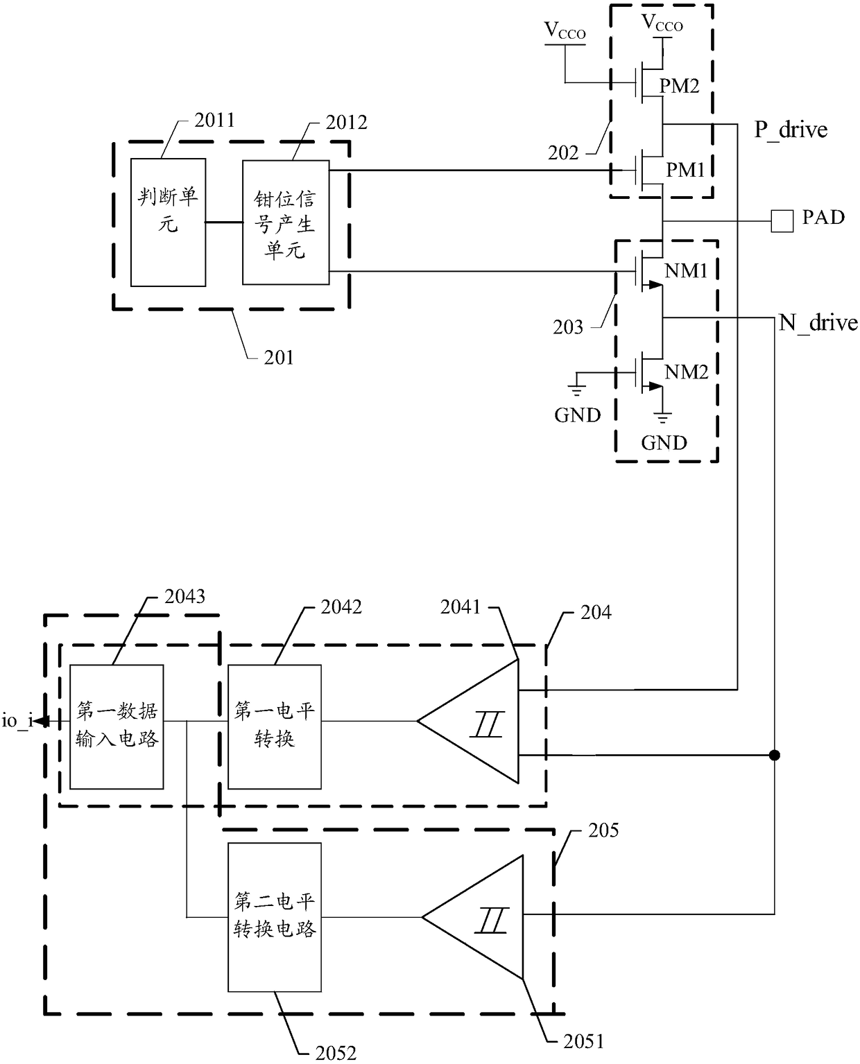
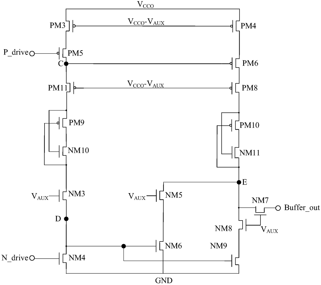
The invention provides an interface circuit. The interface circuit comprises an input circuit. The input circuit comprises a clamping circuit unit, an input buffer unit and a first output driving unitcoupled to the clamping circuit unit and the input buffer unit. The clamping circuit unit is suitable for clamping a port voltage of the first output driving unit within a corresponding device voltage withstand range when the port power voltage of the interface circuit is larger than a preset auxiliary power supply voltage. According to the scheme above, the input voltage range of the input circuit in the interface circuit can be improved.

Description

technical field [0001] The invention relates to the technical field of circuits, in particular to an interface circuit. Background technique [0002] Input and output (I / O) circuits, also known as interface circuits, are usually composed of input circuits and output circuits, which are used to convert voltage swing signals from external circuits into digital signals that can be recognized by integrated circuits or digital signals inside the chip. The signal is converted to an external level voltage signal through the output interface circuit. [0003] However, the existing input circuit is limited by the withstand voltage condition of the port device, so that the input circuit can only realize a small high-voltage swing signal, which limits the application range of the input circuit and the output circuit. Contents of the invention [0004] The problem solved by the embodiments of the present invention is how to increase the input voltage range of the input circuit in the...

Claims


Application Information

Patent Timeline
IPC IPC(8): H03K19/0185
CPCH03K19/018507
Inventor 刘跃智沈磊方刘禄黄月娥张伟国
Owner SHANGHAI FUDAN MICROELECTRONICS GROUP
Why Eureka
Try Eureka