Automatic mining dust removal apparatus

A dust removal device and automatic technology, which is applied in the direction of dust removal, combination device, and separation of dispersed particles, can solve the problems of increasing operating costs for operators, affecting the dust collection function of the dust collection plate, and blockage of the spray pipe nozzle, etc., reaching a good market Competitiveness, simple structure, effect of prolonging service life

Inactive Publication Date: 2018-06-12
成都伍加玖网络科技有限公司
View PDF0 Cites 1 Cited by
  • Summary
  • Abstract
  • Description
  • Claims
  • Application Information

AI Technical Summary

Problems solved by technology

[0002] When mining iron ore, it is necessary to use rock drills to drill rocks, drill holes, and then load them with explosives for blasting. The ore after blasting will be transported to the beneficiation plant with a forklift truck; dust, noise, and CO, SO2, and NOX will be generated during the blasting process. and other gas pollutants, gravel and stripped soil formed by mining will generate dust with the wind, ore transportation will also generate road dust, and ore transportation will also generate road dust. At present, most iron ore crushing sections are set up outdoors, and generally no Prevention and control measures, mine dust has become the biggest problem in the lives of nearby residents. The roads near the mining site are gray all the year round, and choking dust and exhaust gas are floating in the air. A layer of dust, especially when the wind is strong in spring, the amount of dust will increase, which will affect the lives of residents near the dressing plant. For the physical and mental health of residents, mining dust removal has become an indispensable step. The existing automatic mining dust removal device The production process is becoming more and more sophisticated, but there are still some deficie

Method used


Image

  • Automatic mining dust removal apparatus
  • Automatic mining dust removal apparatus
  • Automatic mining dust removal apparatus

Examples


Embodiment Construction

[0018] The following will clearly and completely describe the technical solutions in the embodiments of the present invention with reference to the accompanying drawings in the embodiments of the present invention. Obviously, the described embodiments are only some, not all, embodiments of the present invention. Based on the embodiments of the present invention, all other embodiments obtained by persons of ordinary skill in the art without making creative efforts belong to the protection scope of the present invention.

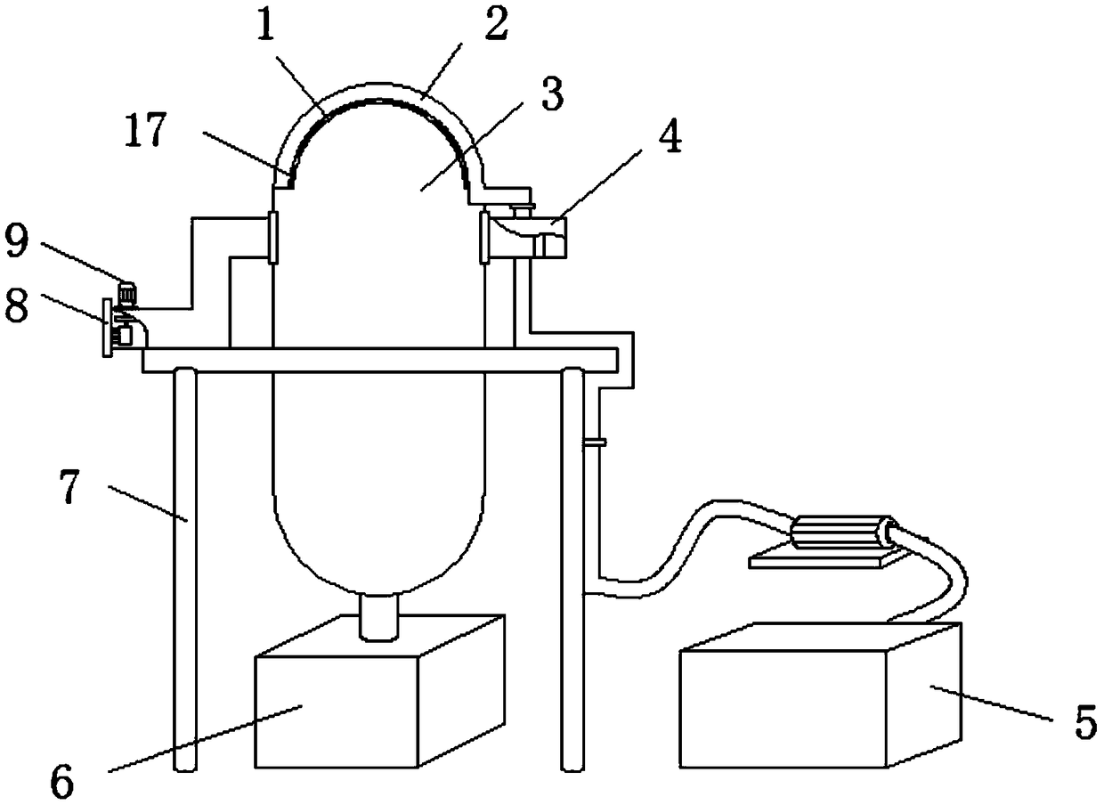
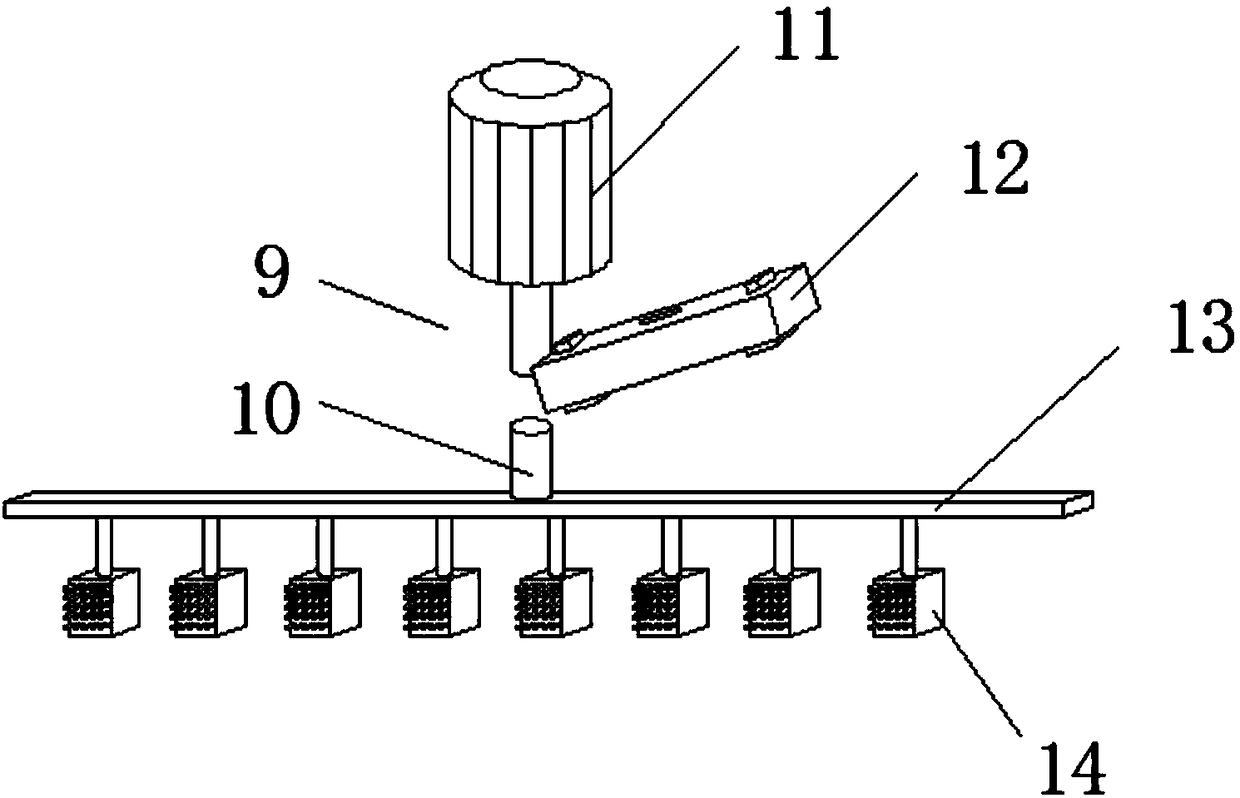
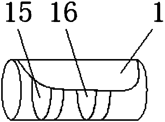
[0019] see Figure 1-3 , the present invention provides the following technical solutions: an automatic mining dust removal device, comprising a bracket 7 and a cleaning device 9, the inside of the bracket 7 is provided with a dust removal tank 3, and one side of the dust removal tank 3 is provided with a cleaning device 9, and the dust removal tank 3 The other side is provided with a draft pipe 4, and the inside of the draft pipe 4 is provided with a draft fa...


PUM


Abstract

The invention discloses an automatic mining dust removal apparatus. The automatic mining dust removal apparatus comprises a support and a cleaning apparatus, wherein a dust removal tank is arranged inside the support, one side of the dust removal tank is provided with the cleaning apparatus, the other side of the dust removal tank is provided with an intake pipe, the cleaning apparatus comprises adriving rod, a lifting motor, a coupler, an installation plate and a brush, one side of the lifting motor is provided with the driving rod, one side, away from the lifting motor, of the driving rod is provided with the installation plate, and one side, away from the driving rod, of the installation plate is provided with the brush. By virtue of the lifting motor structure, the lifting function ofa connecting rod is realized; by virtue of the connecting rod and the brush, a dust collection plate can be automatically cleaned; and the structure is simple, the operation is convenient, the problem that partial dust is accumulated inside the dust collection plate is avoided, the dust collection plate is unnecessary to replace frequently, the labor intensity of the working personnel is alleviated, and the operation cost of the enterprise is reduced.

Description

technical field [0001] The invention belongs to the technical field of dust removal devices, and in particular relates to an automatic mining dust removal device. Background technique [0002] When mining iron ore, it is necessary to use rock drills to drill rocks, drill holes, and then load them with explosives for blasting. The ore after blasting will be transported to the beneficiation plant with a forklift truck; dust, noise, and CO, SO2, and NOX will be generated during the blasting process. and other gas pollutants, gravel and stripped soil formed by mining will generate dust with the wind, ore transportation will also generate road dust, and ore transportation will also generate road dust. At present, most iron ore crushing sections are set up outdoors, and generally no Prevention and control measures, mine dust has become the biggest problem in the lives of nearby residents. The roads near the mining site are gray all the year round, and choking dust and exhaust gas ...

Claims


Application Information

Patent Timeline
IPC IPC(8): B01D50/00B08B15/00
CPCB01D50/00B08B15/00
Inventor 王朝菊
Owner 成都伍加玖网络科技有限公司
Why Eureka
Try Eureka