Efficient sand screening machine used for buildings

A sand screening machine and construction technology, applied in the field of construction machinery, can solve the problems of high labor consumption, clogging of the screen, heavy labor, etc., and achieve the effects of ensuring screening quality, improving sand screening quality, and ensuring efficiency.

Inactive Publication Date: 2018-06-12
KUNSHAN DINGNIU SHIZHENG CONSTR CO LTD
View PDF7 Cites 8 Cited by
  • Summary
  • Abstract
  • Description
  • Claims
  • Application Information

AI Technical Summary

Problems solved by technology

However, the sand screening machines currently on the market are manual, which not only requires a lot of labor, but also has a slow screening efficiency for sand, and some sand will be stuck in the screen. Long-term use will block the screen and need to be cleaned regularly.
[0003] An automatic screening machine disclosed in Chinese Patent Application No. CN201720419883.9, one end of the sand screening box is provided with a sand storage box, and the interior of the sand screening box is symmetrically provided with pulleys, and the pulleys are covered with outlets. The sand board, the outer side of the pulley is sleeved with a belt, although the sand screen can be reciprocated through the meshing action of the gears, so as to achieve the effect of sand screening, but the sand needs to be manually sent into the sand storage box, so require a lot of labor

Method used


Image

  • Efficient sand screening machine used for buildings
  • Efficient sand screening machine used for buildings
  • Efficient sand screening machine used for buildings

Examples


Embodiment

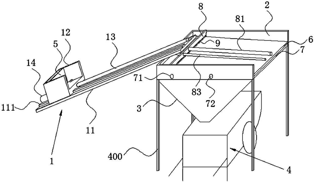
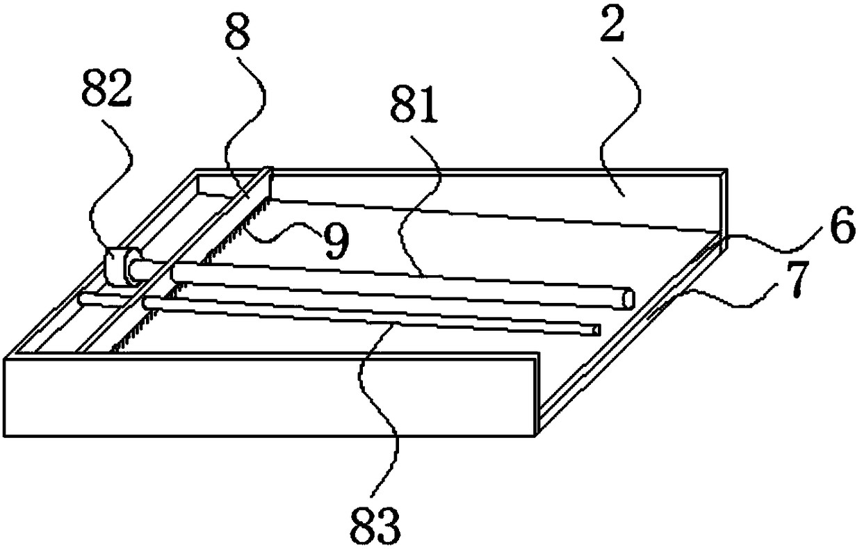
[0033] Example: a high-efficiency sand screening machine for construction, such as Figure 1-Figure 6 As shown, according to the sand screening process, it sequentially includes a feeding mechanism 1, a sand screening tank 2, a sand bucket 3 and a hand-overturned bucket truck 4. The feeding mechanism 1 is located upstream of the sand screening tank 2, and the sand bucket 3 is located below the sand screening tank 2, and the sand bucket 3 is communicated with the sand screening tank 2, and the hand-overturned bucket truck 4 is located below the sand bucket 3;

[0034] During specific implementation, the sand screening tank 2 is fixed on the ground through a support rod 400;

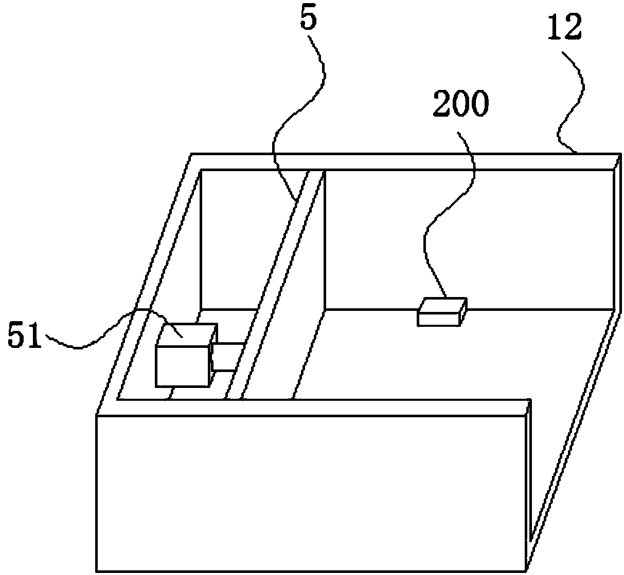
[0035]The feeding mechanism 1 includes a supporting plate 11 , a sand feeding chute 12 , a first screw rod 13 and a feeding driving motor 14 that drives the sand feeding chute 12 to move along the length direction of the supporting plate 11 . The sand tank 12 is located above the support plate 11 , the si...


PUM


Abstract

The invention discloses an efficient sand screening machine used for buildings. The efficient sand screening machine sequentially comprises a feeding mechanism, a sand screening groove, a sand hopperand a tilting cart according to the screening process of sand. The feeding mechanism is located on the upstream portion of the sand screening groove. The sand hopper is located below the sand screening groove and further communicates with the sand screening groove. The tilting cart is located below the sand hopper. The feeding mechanism comprises a supporting plate, a sand conveying groove, a first screw rod and a feeding drive motor used for driving the sand conveying groove to move in the length direction of the supporting plate. The sand conveying groove is located in the upper side of thesupporting plate. The side wall, close to the sand screening groove, of the side walls of the sand conveying groove is opened. The supporting plate is obliquely arranged. The lower end of the supporting plate is fixed to the ground, and the upper end of the supporting plate is located above the sand screening groove. According to the efficient sand screening machine used for the buildings, the labor intensity is low, the screening efficiency of the sand is high, the sand can be prevented from blocking screen holes, impurities like stone blocked into the screen holes can be removed, the particle size of the screened sand can be adjusted at any time, and the screening efficiency and screening quality are guaranteed.

Description

technical field [0001] The invention belongs to the technical field of construction machinery, in particular to a high-efficiency sand screening machine for construction. Background technique [0002] In the construction of construction projects, sand is one of the important raw materials. The sand is salvaged from the river and needs to be screened to screen out the stones and other debris from the sand to ensure the follow-up work. The traditional artificial sand screening is a The screen is tilted and supported on the ground, and then the sand is poured on the top of the screen. During the process of the sand sliding on the screen, the sand smaller than the screen hole passes through the screen, and the sand larger than the screen hole is filtered and slides to the bottom of the screen. . With the step-by-step expansion of infrastructure construction, the demand for sand screening is also increasing. However, the current sand screening machines on the market are manual,...

Claims


Application Information

Patent Timeline
Patent Type & Authority Applications(China)
IPC IPC(8): B07B1/04B07B1/42B07B1/46B07B1/52
CPCB07B1/04B07B1/42B07B1/46B07B1/4636B07B1/522
Inventor 刘西平
Owner KUNSHAN DINGNIU SHIZHENG CONSTR CO LTD
Why Eureka
Try Eureka