
Superconductive magnetic separating device

A separation device and superconducting magnet technology, which are applied in the fields of magnetic separation, solid separation, chemical instruments and methods, etc., can solve the problems of low processing capacity of the separator, easy blockage, and inability to use solenoid superconducting magnets, etc.

Active Publication Date: 2010-12-22
江苏旌凯中科超导高技术有限公司
View PDF5 Cites 16 Cited by
  • Summary
  • Abstract
  • Description
  • Claims
  • Application Information

AI Technical Summary

Problems solved by technology

Due to the reciprocating tank type, intermittent feeding and discharging, it belongs to the intermittent production mode. The disadvantages of intermittent production are low production efficiency and complicated operation.
In addition, this kind of magnetic separator uses steel wool, and the gap between the steel wool is easy to block, which also reduces the processing capacity of the separator.
Therefore, although this superconducting magnetic separator can achieve good results in the removal of traces of ferromagnetic materials in kaolin, it is difficult to extract iron ore from lean ore and extract iron ore from red mud. Due to the high iron content in these materials, the amount of separated iron ore is relatively large, which makes the steel wool clogged faster, the running time is too short, and the efficiency is too low, so it is difficult to apply to iron ore separation.
[0018] However, magnetic separators with horizontal plane turntable or vertical turntable cannot use solenoid superconducting magnets, usually permanent magnets or permanent magnets, with low magnetic field strength and gradient, so it is difficult to separate weak magnetic particles and fine particle minerals

Method used


Image

  • Superconductive magnetic separating device
  • Superconductive magnetic separating device
  • Superconductive magnetic separating device

Examples


Embodiment Construction

[0032] The present invention will be described in further detail below through specific examples, so as to help to understand the content of the present invention.

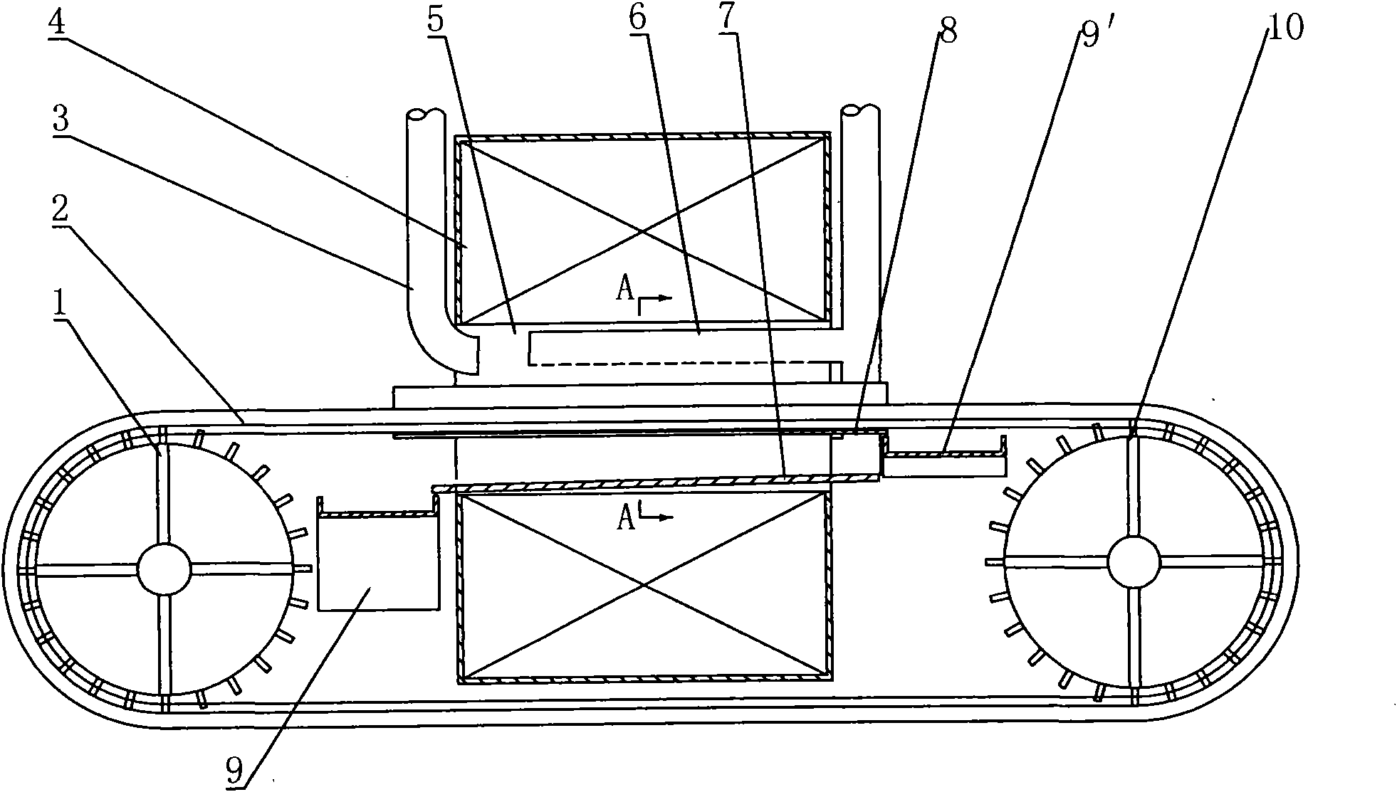
[0033] Such as figure 1 Shown is a superconducting magnetic separation device, including:

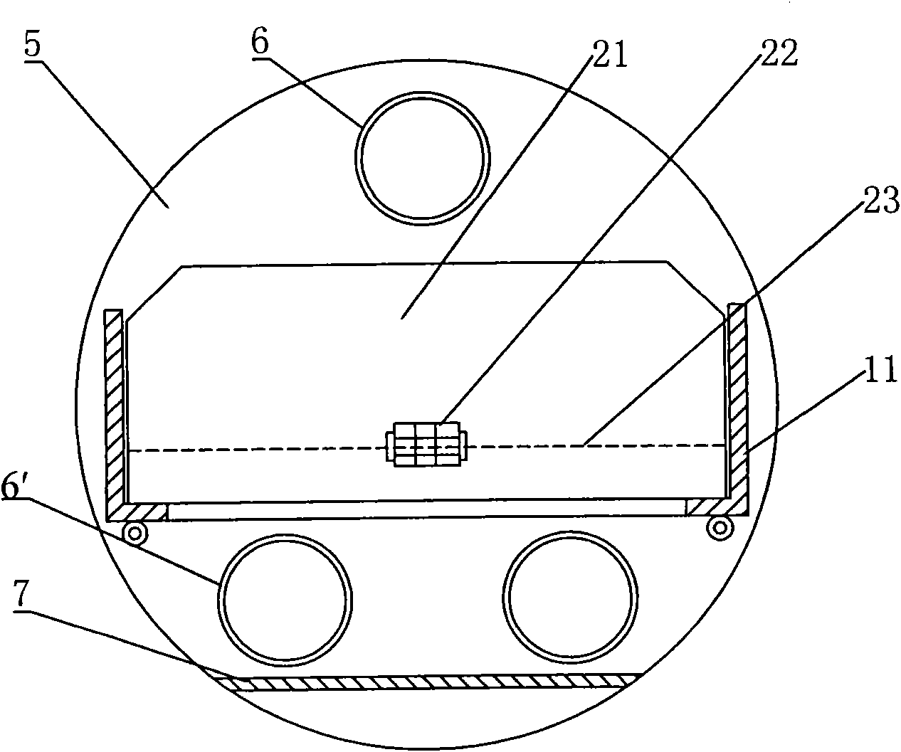
[0034] Solenoid-type superconducting magnet 4 The present invention adopts a solenoid-type superconducting magnet. In its aperture at room temperature, the magnetic field intensity is basically uniform on the axis, and the magnetic field in some selected areas is generally 4-6T. The wire tube winding is cooled by liquid helium (temperature is 4.2K), and the periphery of the superconducting winding is surrounded by a high vacuum layer, a 40K thermal barrier layer and 1 to 2 sets of multilayer insulation layers, and a 4K refrigerator is used to maintain the liquid helium. This kind of superconducting magnet has a magnetic field of 4-6T in the separation area in the hole at room temperature, and the magnetic susceptibility c...


PUM


Abstract

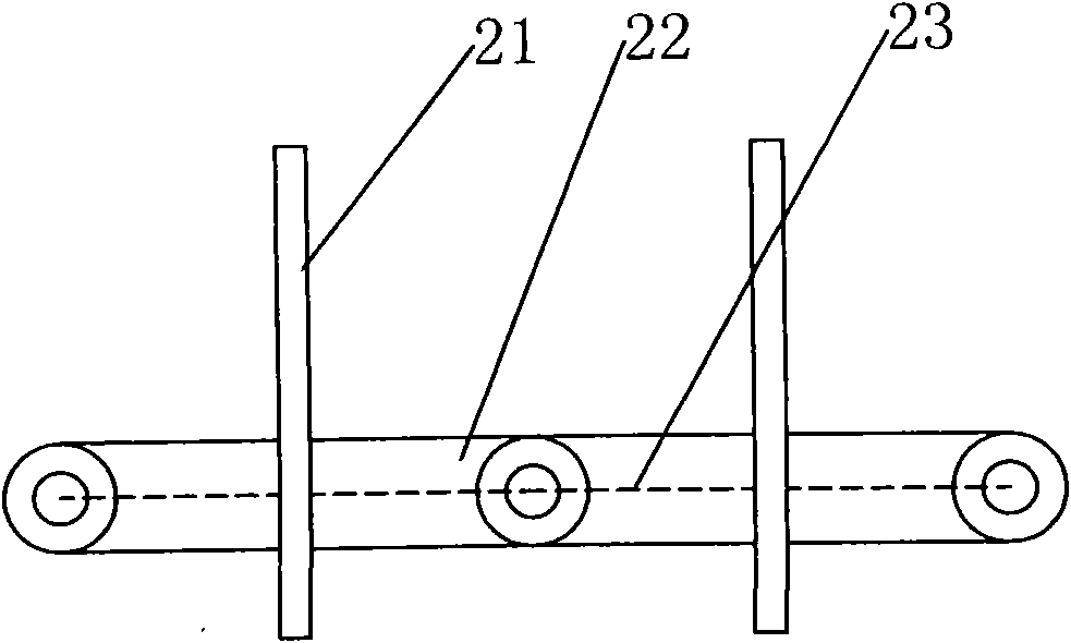
The invention relates to a superconductive magnetic separating device which comprises a solenoid superconductive magnet, a driving wheel and a driven wheel, wherein an annular closed screen type conveyer belt is wound on the driving wheel and the driven wheel, and the bearing surface of the screen type conveyer belt is a screen; and a part of the screen type conveyer belt passes through a room temperature hole of the superconductive magnet, and another part is positioned outside the superconductive magnet. The superconductive magnetic separating device can realize continuous production and greatly improve the separating efficiency; and meanwhile, the solenoid superconductive magnet is adopted, thus the background magnetic field intensity is high, and the separating effect is good; and the superconductive magnetic separating device can be used for treating weakly magnetic materials and fine mineral powder, extracting and separating high-grad iron ore deposits, low-grid iron ore deposits and tainings from iron ore and iron ore from red mud and has high separating efficiency and small separable mineral powder granularity.

Description

technical field [0001] The invention relates to a magnetic separation device, in particular to a superconducting magnetic separation device which can be used for ore dressing. Background technique [0002] Since Franz invented the magnetic separation device for mineral processing in 1937, magnetic separation and mineral processing technology has been greatly developed. In particular, superconducting magnetic separation and separation devices have been used in the mining industry for more than 30 years. Superconducting technology and magnetic separation technology have continued to develop, interpenetrate, integrate and promote each other, making the application of magnetic separation technology more and more extensive. The rapid development of magnetic separation beneficiation technology is based on several reasons: [0003] 1. The magnetic separation mineral processing process is a physical separation method. Compared with the chemical method, the magnetic separation techn...

Claims


Application Information

Patent Timeline
Patent Type & Authority Applications(China)
IPC IPC(8): B03C1/22
Inventor 陈文华栾兆坤马仲英易钢王军
Owner 江苏旌凯中科超导高技术有限公司
Learn More