
Forming device

A technology of a forming device and a forming mechanism, which is applied to the forming device for a forming device and the field of automatic feeding of metal powder metallurgy, can solve the problem that the pressure and extrusion speed cannot be reached, the feeding accuracy of powder metallurgy cannot be automatically controlled, and the metal powder can not be automatically controlled. Powder molding and other problems, to achieve the effect of fast feeding, avoiding metal powder loss, and high stability

Active Publication Date: 2018-06-12
浙江东泰阀门有限公司
View PDF4 Cites 0 Cited by
  • Summary
  • Abstract
  • Description
  • Claims
  • Application Information

AI Technical Summary

Problems solved by technology

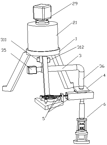
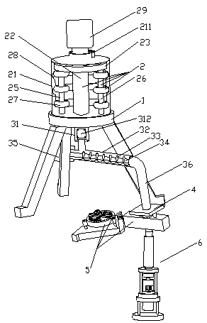
[0008] The inventive idea of ​​the present invention is: in view of the current powder metallurgy production, the powder metallurgy process adopts coarser powders larger than 40 microns, which cannot meet the metallurgical production requirements of good surface activity, high adsorption force, and Cuihua ability, and the powder metallurgy feeding accuracy Due to the inability to achieve automatic control, and the problem that the predetermined pressure and extrusion speed cannot be reached in a short period of time, which affects the forming of metal powder, the present invention designs an automatic feeding and forming device for metal powder metallurgy, a metal powder metallurgy Automatic feeding and forming device, including frame, crushing mechanism, feeding mechanism, weighing mechanism and limit leakage mechanism; pour metal powder from the feeding port into the metal powder feeding bin, and pass through the turntable of the grinding mechanism in turn A through hole, the feeding metal powder leaks into the grinding track and is ground by the grinding disc. The ground metal powder is transported to the metal powder feeding bin of the feeding mechanism through the leaking pipe, and the feeding metal is transported by the spiral blade. The powder is transported to the feeding tube in the middle of the weighing pad of the weighing mechanism. When the weight sensor determines that the amount of metal powder fed reaches the weight set by the metal forming standard, the reduction motor B is turned on, and the moving gear moves along the fixed ring. The inner surface moves, and at the same time, it drives the limit block at the end of the drive rod to move along the shell to the base. All the metal powder falls into the hollow cylindrical syringe in the fixed chamber. Under the action of the elastic recovery force of the return spring, the metal powder in the hollow cylindrical syringe is injected into the hollow through the metal powder leakage channel set at the center of the upper part of the fixed mold. In the cylinder, at this time, the hydraulic cylinder drives the piston rod to move upward, the lower chassis and the lower stamping die are separated from the support frame, and at the same time the piston rod drives the extrusion block to move upward, and the extrusion block and the elastic support element together drive the lower stamping die to move upward until The extrusion groove cooperates with the hollow cylinder to realize the rapid extrusion molding process. The piston rod moves downward, and the lower chassis and the lower stamping die return to the original position. At this time, the piston rod moves upward again to drive the extrusion block along the moving rod A , the moving rod B and the ejector rod move upwards to push out the metal module formed in the hollow cylinder and make it break away from the hollow cylinder. The bottom surface of the rectangular groove of the lower stamping die is in contact with each other, and the limit of the next feeding metal powder is repeated in this way, so as to accurately and quickly control the feeding accuracy of the metal and the forming process of the metal powder

Method used


Image

  • Forming device
  • Forming device
  • Forming device

Examples


Embodiment 1

[0043] see figure 1 , figure 2 , image 3 , Figure 4 , Figure 5 , Figure 6 , Figure 7 , Figure 8 , Figure 9 , Figure 10 , Figure 11 and Figure 12 , the present invention is: an automatic feeding and forming device for metal powder metallurgy, which includes a frame 1, a crushing mechanism 2, a feeding mechanism 3, a weighing mechanism 4 and a position-limiting leakage mechanism 5;

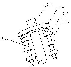
[0044] The crushing mechanism 2 includes a metal powder upper hopper 21 with a feeding port 211 on the top, and a grinding mechanism arranged in the metal powder upper hopper 21. The grinding mechanism includes a drive shaft 22, a turntable A23 arranged on the drive shaft 22, and a turntable A23. A number of through holes are evenly arranged, and vertical rods A25 and vertical rods B26 are arranged on the bottom surface of the turntable A23. There are several grinding discs 27 at equal intervals on the vertical rods A25 and vertical rods B26 respectively. The grinding track 28 ...


PUM


Abstract

The invention discloses a forming device and belongs to the technical field of metallurgical equipment. According to the technical scheme, the forming device comprises a forming mechanism, wherein theforming mechanism comprises a supporting frame, a hydraulic cylinder, a lower punching die mechanism, a fixing die and a metal powder injection mechanism; the hydraulic cylinder is fixed on the supporting frame; the lower punching die mechanism is connected to the top end of a piston rod of the hydraulic rod; the fixing die is arranged on the supporting frame and positioned above the lower punching die mechanism; and the metal powder injection mechanism is arranged above the fixing die. The forming device disclosed by the invention has the following beneficial effects: through the mutual extrusion between the fixing die and a lower punching die of the lower punching die mechanism, metal powder can be quickly formed into a metal block; through the arrangement of an elastic supporting element, the formed metal block can be ejected from a hollow cylinder; through the hydraulic cylinder, the preset pressure and extrusion speed of the lower punching die can be reached within a short time;the continuous forming of qualifiedly-measured metal powder can be facilitated; and accordingly, the forming device is suitable for batch production.

Description

[0001] This case is a divisional application. The invention name of the original application is: an automatic feeding and forming device for metal powder metallurgy. The filing date of the original application is: 2016-09-07, and the application number of the original application is: 201610805720.4. technical field [0002] The invention relates to the technical field of metallurgical equipment, in particular to a forming device for automatic feeding and forming devices for metal powder metallurgy. Background technique [0003] In powder metallurgy production, the particle size of metal powder is generally required to be 0.5-20 microns, because theoretically speaking, the finer the particles, the larger the specific surface area, and its surface effects, such as surface activity, surface adsorption capacity, catalytic ability, etc. stronger. The easier it is to form and sinter, the traditional powder metallurgy process generally uses coarser powders larger than 40 microns, w...

Claims


Application Information

Patent Timeline
Patent Type & Authority Applications(China)
IPC IPC(8): B22F3/00B22F3/20B22F3/22
CPCB22F3/005B22F3/20B22F3/225
Inventor 于海青
Owner 浙江东泰阀门有限公司
Learn More