
Numerical control machine tool

A technology of CNC machine tools and racks, which is applied in the field of CNC machine tools, and can solve problems such as easy deformation, longitudinal deviation, and fracture of the side walls of slide rails

Active Publication Date: 2018-06-12
台州新发自动化设备有限公司
View PDF1 Cites 2 Cited by
  • Summary
  • Abstract
  • Description
  • Claims
  • Application Information

AI Technical Summary

Problems solved by technology

The first force component makes the cross slide have a tendency to slide downward along the slope, so that when the CNC machine tool is used to process the workpiece, the side wall of the slide rail is squeezed from the cross slide, so that the side of the slide rail The wall is prone to deformation or even fracture
In this way, when the cross slide rail moves on the slide rail, it is easy to deviate in the longitudinal direction, which has a great impact on the machining accuracy of the CNC machine tool.

Method used


Image

  • Numerical control machine tool
  • Numerical control machine tool
  • Numerical control machine tool

Examples


Embodiment 2

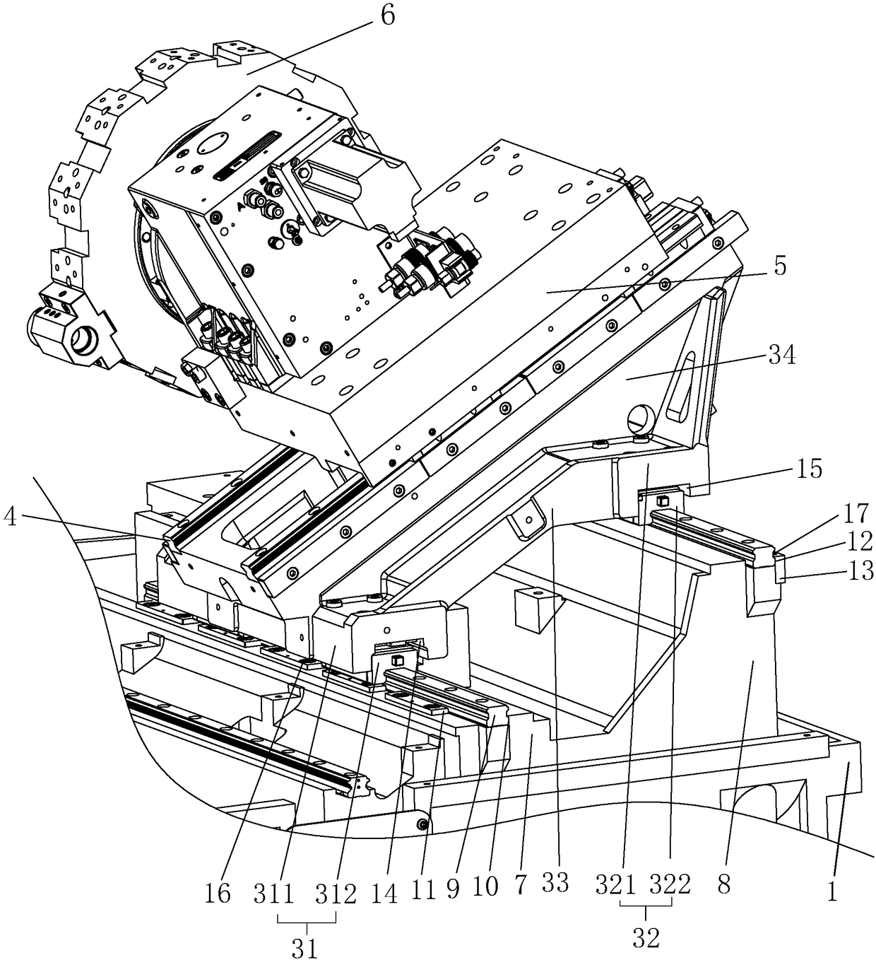
[0046] Such as Figure 5 , Figure 6 As shown, the difference between Embodiment 2 and Embodiment 1 is that a receiving groove 21 is provided on the top surfaces of the first track seat 7 and the second track seat 8, and the length direction of the receiving groove 21 is parallel to the first track seat 7 and the first track seat 8. The second track seat 8. A plurality of grooves 22 are arranged on the inner groove wall of the receiving groove 21 , and the grooves 22 vertically penetrate the top surface of the first track seat 7 or the second track seat 8 . The grooves 22 are evenly divided into two groups and symmetrically distributed on the inner groove walls on both sides of the storage groove 21 , and the grooves 22 are evenly distributed along the length direction of the storage groove 21 .

[0047] A hinge plate 23 is hinged inside the groove 22 , and the rotation axis of the hinge plate 23 is parallel to the receiving groove 21 . A supporting plate 24 and a resisting...


PUM


Abstract

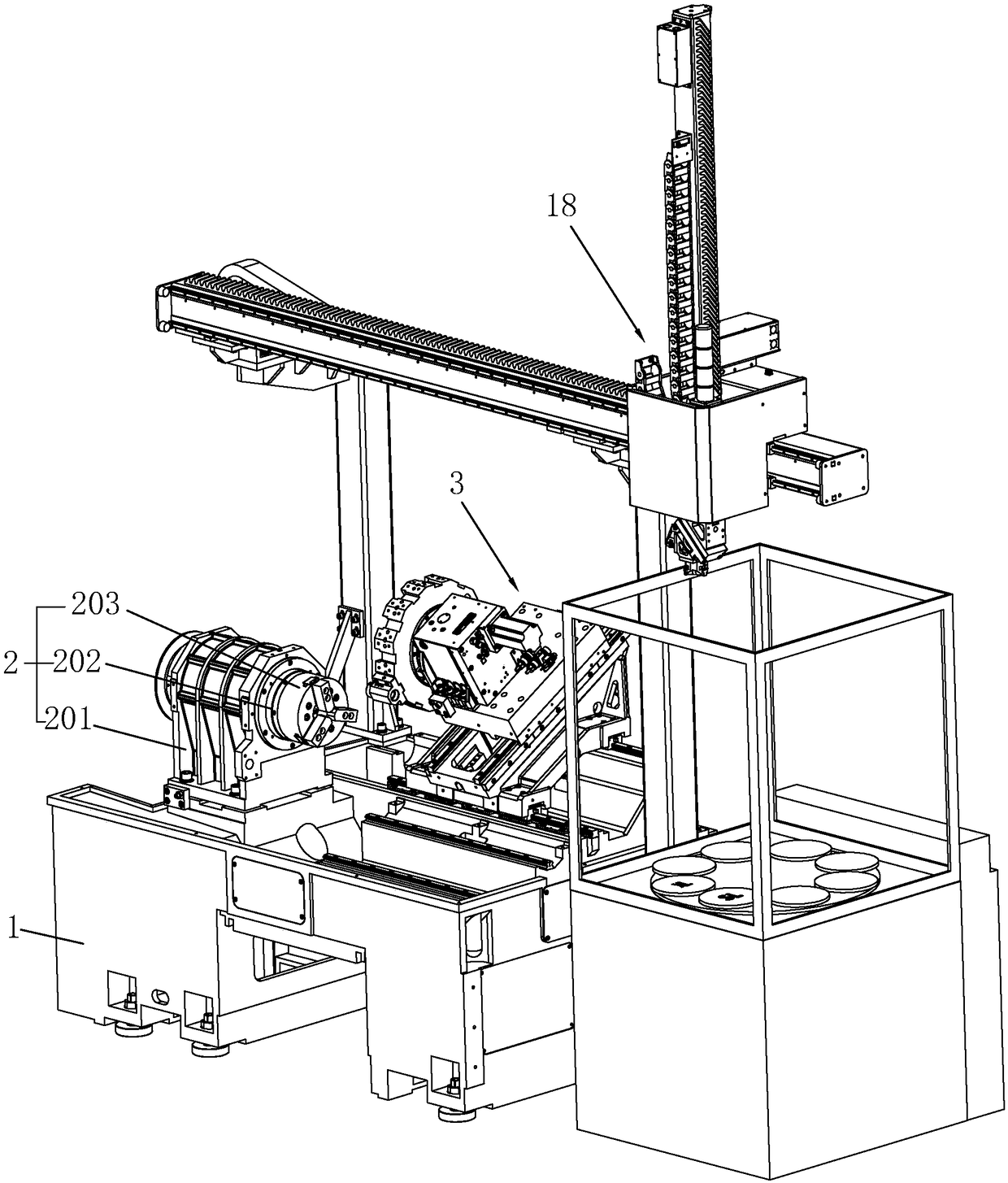
The invention discloses a numerical control machine tool. The Key points of the technical scheme of the numerical control machine tool are that the numerical control machine tool comprises a machine frame, a clamp, a sliding saddle, a longitudinal sliding rail, a sliding plate and a rotary knife rest; a first rail seat and a second rail seat are arranged on the machine frame in parallel, and the second rail seat is higher than the first rail seat; transverse sliding rails perpendicular to the longitudinal sliding rail are arranged on the first rail seat and the second rail seat respectively; and the sliding saddle is slidingly connected between the first rail seat and the second rail seat; the top surface of the transverse sliding rail on the first rail seat and the top surface of the transverse sliding rail on the second rail seat are both horizontal surfaces so as to enable the contact surfaces of the sliding saddle and the transverse sliding rails are also horizontal planes, so thatthe gravity of the sliding saddle directly acts on the top surfaces of the transverse sliding rails; the gravity direction of the sliding saddle is perpendicular to the top surfaces of the transversesliding rails, so that the sliding saddle is not prone to generating the trend of longitudinal movement and vertical movement in the moving process, and therefore the side walls of the transverse sliding rails are not prone to deformation and even damage, and machining precision of the numerical control machine tool is guaranteed to a certain degree.

Description

technical field [0001] The invention relates to the technical field of workpiece processing equipment, in particular to a numerically controlled machine tool. Background technique [0002] CNC machine tool is an automatic machine tool equipped with a program control system. [0003] At present, the Chinese patent with the notification number CN205817305U discloses a double-headed CNC machine tool, which includes a bed with an inclined surface, a slide rail is arranged on the inclined surface, and the top surface of the slide rail is parallel to the inclined surface. A cross sliding table is slidably connected to the slide rail, and the top surface of the cross sliding table is parallel to the inclined surface, a rotary tool rest is arranged on the cross sliding table, and a Z-axis motor is arranged on the bed, and the Z-axis motor is used for Drive the cross slide to slide on the slide rail, the cross slide is provided with an X-axis motor, the X-axis motor is used to drive...

Claims


Application Information

Patent Timeline
IPC IPC(8): B23Q1/01
CPCB23Q1/015B23Q1/017
Inventor 应宗连
Owner 台州新发自动化设备有限公司
Learn More