Hydraulic CNG gas cylinder fixing device

A fixing device, hydraulic technology, applied in the field of hydraulic CNG gas cylinder fixing device, can solve the problems of high processing cost, inconvenient assembly, large error of bottle length and diameter, etc., achieve reasonable structural design, wide application range, good adjustability

Pending Publication Date: 2018-06-12
TIANJIN LIANGHUA NEW ENERGY TECH
View PDF6 Cites 1 Cited by
  • Summary
  • Abstract
  • Description
  • Claims
  • Application Information

AI Technical Summary

Problems solved by technology

[0002] The gas cylinders on the existing natural gas transport vehicles are mainly fixed by hoops in the middle of the gas cylinder body, and the two ends of the gas cylinder body are limited by retaining rings. This fixing method has the following defects: each gas cylinder During the processing of the bottle, the error of the bottle length and diameter is relatively large; therefore, the size of the fixing structure of the gas cylinder on different vehicles is not uniform, resulting in high processing costs, and the fixing of the compressed natural gas cylinder (CNG cylinder) on the vehicle has the problem of under-positioning , resulting in the possibility of potential cylinder displacement during the long-term operation of the vehicle. During the production process of the vehicle, due to the heavy weight of the commonly used CNG cylinders, it is inconvenient to assemble the CNG cylinders on the vehicle one by one, which reduces the production efficiency of the vehicle.

Method used


Image

  • Hydraulic CNG gas cylinder fixing device
  • Hydraulic CNG gas cylinder fixing device

Examples


Embodiment Construction

[0016] It should be noted that, in the case of no conflict, the embodiments of the present invention and the features in the embodiments can be combined with each other.

[0017] In describing the present invention, it should be understood that the terms "center", "longitudinal", "transverse", "upper", "lower", "front", "rear", "left", "right", " The orientations or positional relationships indicated by "vertical", "horizontal", "top", "bottom", "inner" and "outer" are based on the orientations or positional relationships shown in the drawings, and are only for the convenience of describing the present invention and Simplified descriptions, rather than indicating or implying that the device or element referred to must have a particular orientation, be constructed and operate in a particular orientation, and thus should not be construed as limiting the invention. In addition, the terms "first", "second", etc. are used for descriptive purposes only, and should not be understood ...


PUM


Abstract

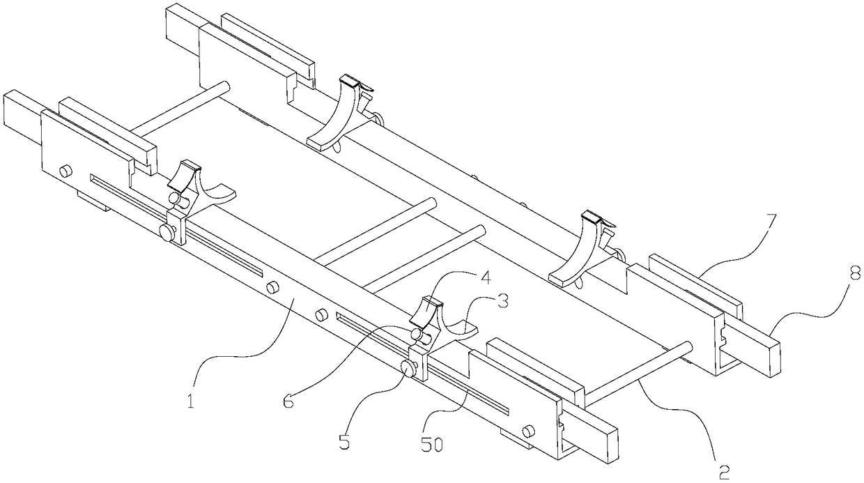
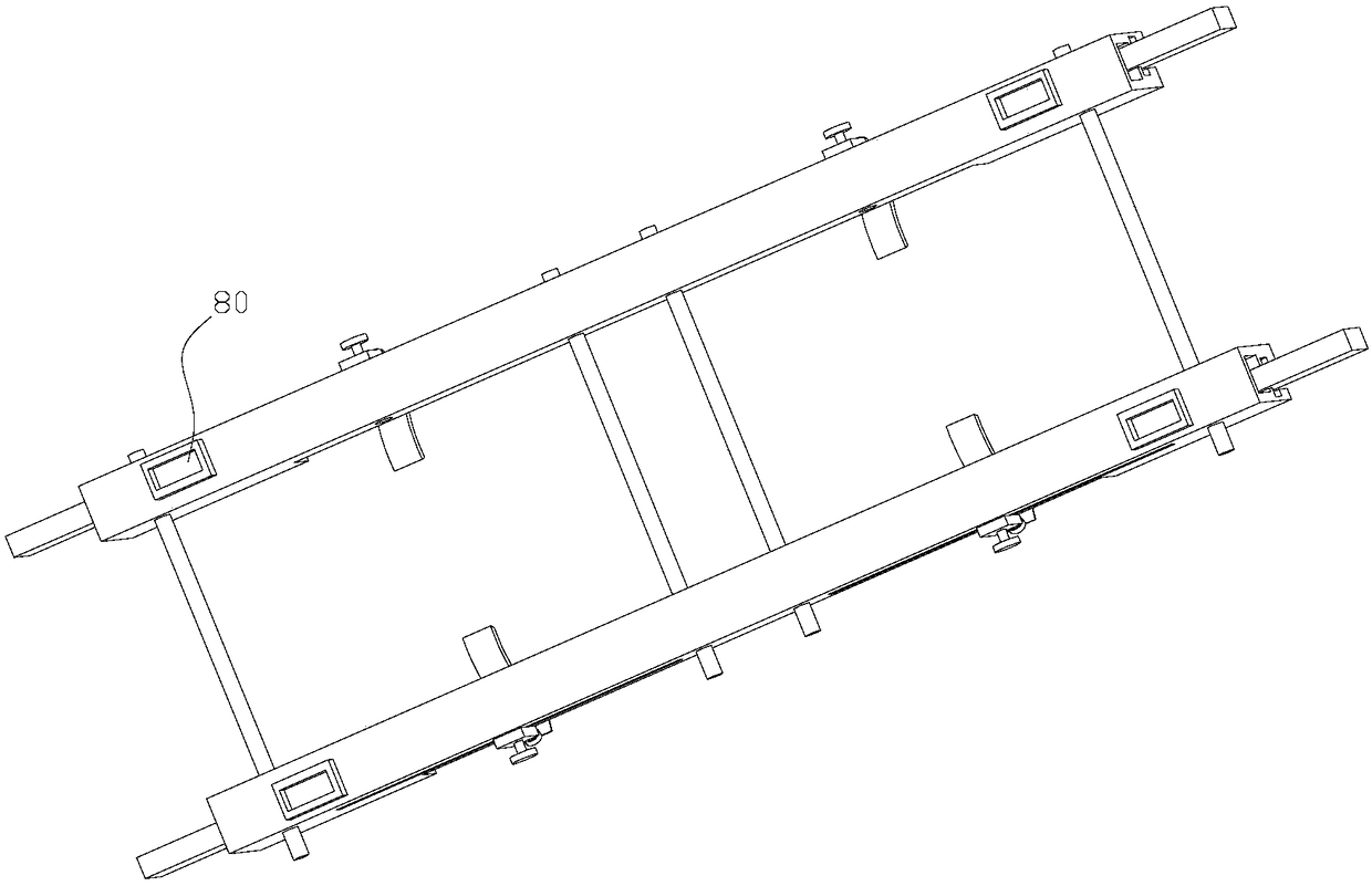
The invention provides a hydraulic CNG gas cylinder fixing device. The hydraulic CNG gas cylinder fixing device comprises main beams, connecting beams, cylinder brackets, adjusting bolts, clamping grooves and supporting beams. The two main beams are arranged in parallel. The connecting beams are connected with the two main beams. An interval between the two main beams can be adjusted. Sliding grooves are formed in the outer sides of the two main beams. The cylinder brackets capable of sliding are arranged on the each of the main beams. The cylinder holders are of an arc bracket structure. Theadjusting bolts are arranged on the cylinder brackets. The adjusting bolts slide freely in the sliding grooves. The clamping grooves are formed in the two end portions of the main beams. The supporting beams are arranged in the clamping grooves in a pull-out mode. The supporting beams can rotate in the clamping grooves. Fixing grooves are formed in a nearby position of the two ends of the bottom portions of the main beams, and the fixing grooves limit the supporting beams to the fixing grooves. The hydraulic CNG gas cylinder fixing device is reasonable in structure design, convenient to use, capable of meeting the fixing of different sizes of the gas cylinders, especially capable of realizing the safe transportation of multi-layer gas cylinders, low in cost, good in adjustment and wider inthe range of application, so that the transportation of natural gas is safer and more efficient.

Description

technical field [0001] The invention belongs to the technical field of natural gas transportation, in particular to a hydraulic CNG cylinder fixing device. Background technique [0002] The gas cylinders on the existing natural gas transport vehicles are mainly fixed by hoops in the middle of the gas cylinder body, and the two ends of the gas cylinder body are limited by retaining rings. This fixing method has the following defects: each gas cylinder During the processing of the bottle, the error of the bottle length and diameter is relatively large; therefore, the size of the fixing structure of the gas cylinder on different vehicles is not uniform, resulting in high processing costs, and the fixing of the compressed natural gas cylinder (CNG cylinder) on the vehicle has the problem of under-positioning , resulting in the possibility of potential cylinder displacement during the long-term operation of the vehicle. During the production process of the vehicle, due to the hea...

Claims


Application Information

Patent Timeline
Patent Type & Authority Applications(China)
IPC IPC(8): B60K15/07
CPCB60K15/07B60K15/03006
Inventor 史志强
Owner TIANJIN LIANGHUA NEW ENERGY TECH
Why Eureka
Try Eureka