Textile separating equipment and textile separating conveying equipment
A technology of separation equipment and conveying equipment, which is applied in the field of textiles, can solve problems such as poor separation effect and insufficient separation, and achieve the effect of effectively separating textiles
- Summary
- Abstract
- Description
- Claims
- Application Information
AI Technical Summary
Problems solved by technology
Method used
Image

Examples
no. 1 approach >
[0055] Hereinafter, the textile separating device 1 and the textile separating and conveying device according to the first embodiment of the present invention will be described.
[0056] In this embodiment, the textile is conveyed to the sewing machine for sewing as an example, but it is not limited to this, and the textile separated by the textile separating device 1 may also be conveyed to other processes.
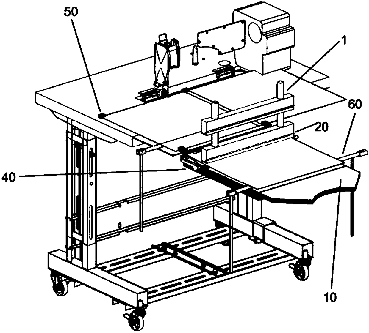
[0057] Such as figure 1 and Figure 15 As shown, the textile separating device 1 is installed on the right side of the sewing machine to work, and the separated textiles are transported to the sewing machine through the clip described later.
[0058] Sewing machine can adopt existing known various sewing machines, omit description here, figure 1 The relative positional relationship between the sewing machine and the textile separating device 1 is only schematically shown, and the sewing machine head and the like are omitted.
[0059] In the description below, the fig...
no. 2 approach >
[0104] Next, a textile separating device 1 and a textile separating and conveying device according to a second embodiment of the present invention will be described. In the second embodiment, descriptions of the same structures as the textile separating device 1 and the textile separating and conveying device in the first embodiment are omitted, and the parts different from those in the first embodiment are mainly explained.
[0105] The main difference between this embodiment and the first embodiment is that, in this embodiment, a separation auxiliary device 60 that assists separation and a transport auxiliary device 60 that assists transportation are provided.
[0106] Wherein, the separation auxiliary device includes at least one of the brush body 70 , the first fan 80A and the second fan 80B. Hereinafter, descriptions will be made by taking an example in which the separation auxiliary device includes only one of the above separation auxiliary devices. But the present inve...
no. 3 approach >
[0118] Next, the textile separating device 1 and the textile separating and conveying device according to the third embodiment of the present invention will be described. In the third embodiment, the same structure as the textile separating device 1 and the textile separating and conveying device in the first embodiment and the second embodiment will be omitted, and the description will be focused on the parts that are different from those in the first embodiment and the second embodiment .
[0119] The main difference between this embodiment and the first embodiment and the second embodiment is that, in this embodiment, the pick-up mechanism with sticky components is used as the textile pick-out unit 30 to replace the needle clip arrangement 310 to pick up textiles.
[0120] The viscous part in this embodiment may include, for example, an adhesive tape, and may also include a body of an adhesive mechanism for fixing the adhesive tape. The body of the adhesive mechanism is con...
PUM
 Abstract
Description
Claims
Application Information
 - R&D
- Intellectual Property
- Life Sciences
- Materials
- Tech Scout
- Unparalleled Data Quality
- Higher Quality Content
- 60% Fewer Hallucinations
Browse by: Latest US Patents, China's latest patents, Technical Efficacy Thesaurus, Application Domain, Technology Topic, Popular Technical Reports.
© 2025 PatSnap. All rights reserved.Legal|Privacy policy|Modern Slavery Act Transparency Statement|Sitemap|About US| Contact US: help@patsnap.com