Combined type magnetron sputtering cathode

A magnetron sputtering and composite technology, applied in the direction of sputtering plating, ion implantation plating, coating, etc., can solve the problems of inflexible adjustment and low utilization rate of targets, so as to improve the utilization rate of targets, Wide range of effects

Active Publication Date: 2018-06-12
INST OF ELECTRICAL ENG CHINESE ACAD OF SCI
View PDF7 Cites 14 Cited by
  • Summary
  • Abstract
  • Description
  • Claims
  • Application Information

AI Technical Summary

Problems solved by technology

[0006] The purpose of the present invention is to overcome the shortcomings of the conventional magnetron sputtering device that the magnetic field on the target surface cannot be flexibly adjusted during use and the utilization rate of the target is low, and propose a composite magnetron sputtering cathode

Method used


Image

  • Combined type magnetron sputtering cathode
  • Combined type magnetron sputtering cathode
  • Combined type magnetron sputtering cathode

Examples


Embodiment Construction

[0028] The present invention will be further described below with reference to the accompanying drawings and specific embodiments.

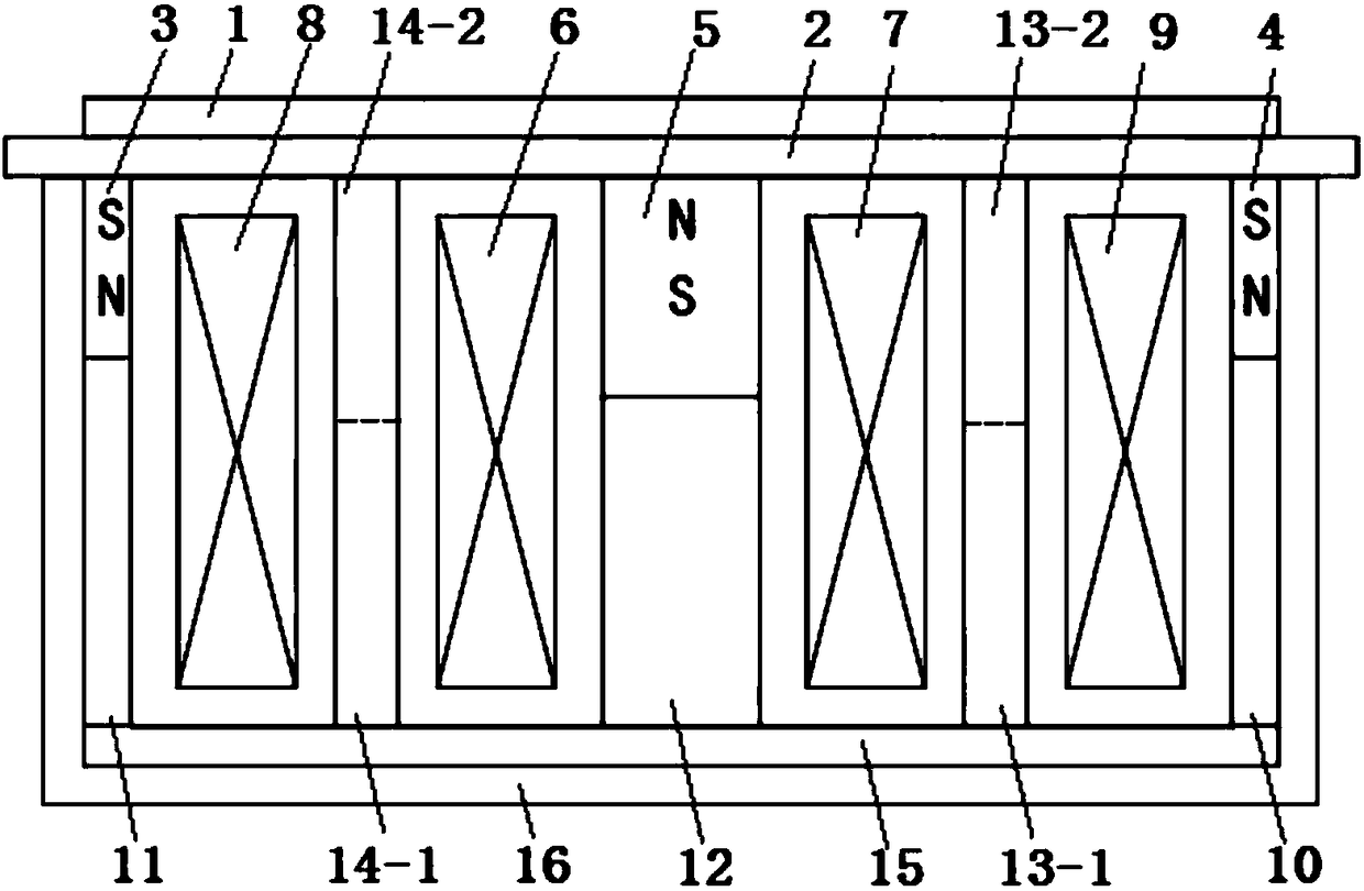
[0029] figure 1 It is a composite magnetron sputtering device of the present invention. like figure 1 As shown, the magnetron sputtering cathode is rectangular and planar, and consists of a planar target 1, a water-cooled back plate 2, outer permanent magnets 3 and 4, inner permanent magnets 5, inner electromagnetic coils 6 and 7, and outer electromagnetic coils. 8 and 9, outer yokes 10 and 11, inner yoke 12, middle yokes 13 and 14, bottom yoke 15 and frame 16 constitute. The water-cooled back plate 2 is installed below the flat target 1, and the upper surface of the water-cooled back plate is provided with a groove, and the groove is filled with cooling water. The outer permanent magnets 3 and 4 are installed under the water-cooled back plate 2 , and the two outer permanent magnets 3 and 4 are placed symmetrically about the center line of the...


PUM


Abstract

The invention relates to a combined type magnetron sputtering cathode which is formed by a plane target material (1), a water cooling back plate (2), outer permanent magnets (3 and 4), an inner permanent magnet (5), inner electromagnetic coils (6 and 7), outer electromagnetic coils (8 and 9), outer yokes (10 and 11), an inner yoke (12), middle yokes (13 and 14), a bottom yoke (15) and a frame (16). A closed coil is formed by the two inner electromagnetic coils (6 and 7), and a closed coil is formed by the two outer electromagnetic coils (8 and 9). The inner electromagnetic coils and the outerelectromagnetic coils are connected to an external power supply through leads. By adjusting the magnitude and the direction of current in the inner electromagnetic coils and the outer electromagneticcoils, changes of magnetic field intensity and distribution on the surface of the magnetron sputtering cathode are achieved, the sputtering speed, the magnetic field unbalance degree are adjusted, andthe target material using rate is increased.

Description

technical field [0001] The invention relates to a magnetron sputtering equipment, in particular to a magnetron sputtering cathode. Background technique [0002] Magnetron sputtering belongs to physical vapor deposition and is widely used in the preparation of functional thin films such as semiconductors, metals, and insulators. Magnetron sputtering includes many types. From the cathode target structure, it can be divided into planar magnetron sputtering target and cylindrical magnetron sputtering target. From the magnetic field distribution of discharge space, it can be divided into balanced target and unbalanced target. The power supply can be divided into DC magnetron sputtering and AC magnetron sputtering. The magnetron sputtering equipment is simple, and the target material used is easy to manufacture and install. The target utilization rate of the planar magnetron sputtering target is very low, the utilization rate of the circular target is generally lower than 10%, a...

Claims


Application Information

Patent Timeline
Patent Type & Authority Applications(China)
IPC IPC(8): C23C14/35H01J37/34
CPCC23C14/3407C23C14/35H01J37/3408H01J37/3417H01J37/345
Inventor 邱清泉汪天龙屈飞靖立伟张国民肖立业
Owner INST OF ELECTRICAL ENG CHINESE ACAD OF SCI
Why Eureka
Try Eureka