Thermodynamic system and small-scale natural gas distributed energy supply system

A thermal system and thermal technology, applied in gas turbine devices, steam generation methods using heat carriers, machines/engines, etc., can solve the problem that industrial users cannot completely match electricity and heat consumption, cannot meet the power needs of industrial enterprises, and cannot use steam. Storage and other problems, to solve the problem of thermal energy can not be stored, improve system economy, save gas consumption

Inactive Publication Date: 2018-06-12
ENN ENERGY SERVICE
View PDF7 Cites 0 Cited by
  • Summary
  • Abstract
  • Description
  • Claims
  • Application Information

AI Technical Summary

Problems solved by technology

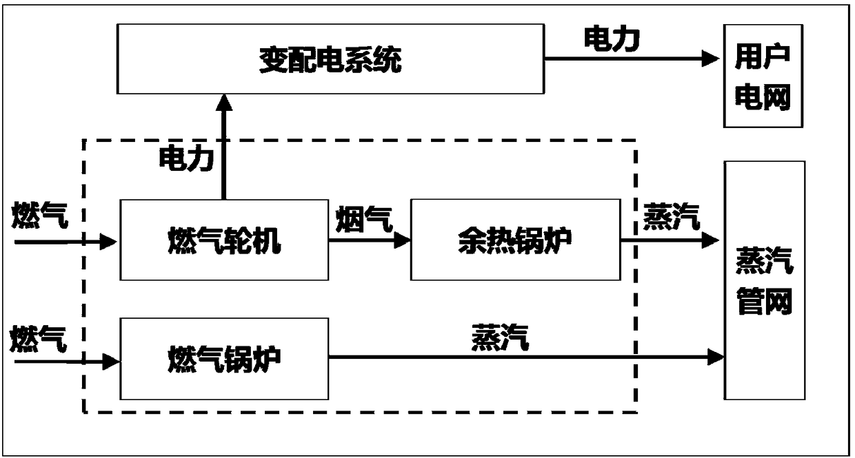
[0006] 1) Some industrial users cannot completely match the electricity and heat consumption, limited by the unstorable nature of steam, the system design can only be based on the principle of "determining electricity by heat", which limits the scale of power generation to a certain extent and cannot meet The power demand of some industrial enterprises that "use more electricity and less heat";
[0007] 2) Restricted by the "peak, flat and valley" electricity price policy implemented by industrial electricity consumption, due to the low electricity price during off-peak hours, the gas turbine cannot operate, and the cost of direct heating by using a gas-fired steam boiler or a gas-fired heat-conducting oil furnace is relatively high, and Uneconomical

Method used


Image

  • Thermodynamic system and small-scale natural gas distributed energy supply system
  • Thermodynamic system and small-scale natural gas distributed energy supply system
  • Thermodynamic system and small-scale natural gas distributed energy supply system

Examples


Embodiment Construction

[0029] Embodiments of the present invention are described in detail below, examples of which are shown in the drawings, wherein the same or similar reference numerals designate the same or similar elements or elements having the same or similar functions throughout. The embodiments described below by referring to the figures are exemplary only for explaining the present invention and should not be construed as limiting the present invention.

[0030] In describing the present invention, it should be understood that the terms "center", "longitudinal", "transverse", "upper", "lower", "front", "rear", "left", "right", " The orientations or positional relationships indicated by "vertical", "horizontal", "top", "bottom", "inner" and "outer" are based on the orientations or positional relationships shown in the drawings, and are only for the convenience of describing the present invention and Simplified descriptions, rather than indicating or implying that the device or element refe...


PUM


Abstract

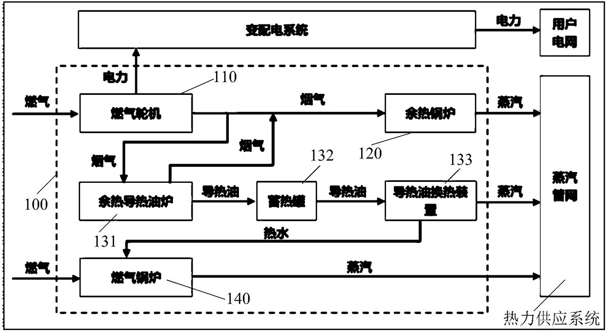
The invention provides a thermodynamic system and a small-scale natural gas distributed energy supply system. The thermodynamic system comprises a gas turbine subsystem, a waste heat utilization subsystem and a heat-conduction oil heat storage subsystem; the gas turbine subsystem is used for generating electric energy according to input gas and outputting the electric energy to an electricity transformation and distribution system, and meanwhile high temperature flue gas is discharged; the waste heat utilization subsystem is connected with the gas turbine subsystem and used for generating steam according to the high-temperature flue gas and outputting the steam to a heat power supply system; and the heat-conduction oil heat storage subsystem is connected with the gas turbine subsystem andused for heating heat-conduction oil according to the residual part of the high-temperature flue gas when the high-temperature flue gas remains, conducting heat preservation and storing the obtained high-temperature heat-conduction oil, and used for generating steam or hot water according to the high-temperature heat-conduction oil and outputting the steam to the heat power supply system when thegas turbine subsystem is shut down. The application range of natural gas distributed energy supply is widened, meanwhile, the economy of the system is improved, flue gas waste heat generated by the turbine subsystem is fully utilized, and the gas consumption of a gas boiler in the off-peak electricity period is reduced.

Description

technical field [0001] The invention relates to the technical field of thermal power supply, in particular to a thermal system and a small-scale natural gas distributed energy supply system. Background technique [0002] At present, natural gas distributed energy supply is in a stage of rapid development. Its focus is to coordinate the actual needs of users with existing conditions, couple existing energy-resource allocation conditions with corresponding energy technologies, and pursue energy and resource utilization efficiency. maximization and optimization. [0003] At present, the small-scale natural gas distributed energy supply system with an installed capacity of less than 20MW is developing more rapidly due to its unique advantages. It is mainly used in buildings, hospitals, factories, data centers and other fields, with great development potential. The utilization of natural gas power generation waste heat has a significant impact on the comprehensive utilization ef...

Claims


Application Information

Patent Timeline
IPC IPC(8): F02C6/00F02C6/18F22B1/18F22B1/16
Inventor 丁广辉刘铜曹浩韩昌
Owner ENN ENERGY SERVICE
Why Eureka
Try Eureka