Common-bus multifunctional mobile energy storage vehicle and control strategy

A mobile energy storage and multi-functional technology, applied in the direction of motor vehicles, electric vehicles, vehicle energy storage, etc., can solve problems such as difficulty in realizing charging of large-scale electric engineering vehicles, difficulty in realizing multi-cluster battery parallel connection, narrow application range of application scenarios, etc. , achieve the effect of alleviating battery life anxiety, improving battery consistency, and reducing large-area laying

Pending Publication Date: 2020-09-29
福建巨电新能源股份有限公司
View PDF1 Cites 6 Cited by
  • Summary
  • Abstract
  • Description
  • Claims
  • Application Information

AI Technical Summary

Problems solved by technology

[0004] The above-mentioned patent is for the electrical structure of a single-cluster battery, it is difficult to realize the parallel connection of multiple cluster batteries, and the installed capacity of the system is small; the auxiliary power acquisition strategy for the independent operation of a single-cluster battery is complex; and the existing energy storage vehicles have single functions, which easily lead to energy storage The vehicle is idle, and the scope of application scenarios is narrow. It is difficult to realize the charging work of large electric engineering vehicles, and it is difficult to apply to the application scenarios with high power load and high power consumption time, etc.

Method used


Image

  • Common-bus multifunctional mobile energy storage vehicle and control strategy
  • Common-bus multifunctional mobile energy storage vehicle and control strategy
  • Common-bus multifunctional mobile energy storage vehicle and control strategy

Examples


Embodiment Construction

[0036] The present invention will be further described in conjunction with the accompanying drawings and specific embodiments.

[0037] The content not described in detail in this specification belongs to the prior art known to those skilled in the art. In the description of the present invention, it should be understood that the terms "first", "second", "third" and so on are only used to distinguish descriptions, and cannot be understood as indicating or implying relative importance.

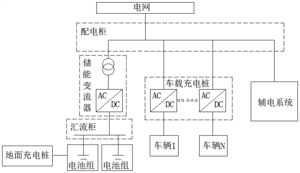
[0038] Such as figure 1As shown, a common bus multifunctional mobile energy storage vehicle provided in this embodiment is a container structure, including a vehicle body and an energy storage assembly, the energy storage assembly is arranged on the vehicle body, and the energy storage assembly includes a battery assembly, a confluence cabinet, power storage converter (PCS), power distribution cabinet, on-board charging pile, control system, and auxiliary power system, the battery assembly is ...


PUM


Abstract

The invention discloses a common-bus multifunctional mobile energy storage vehicle and a control strategy, and belongs to the power supply equipment field. The common-bus multifunctional mobile energystorage vehicle comprises a vehicle body and an energy storage assembly. The energy storage assembly is arranged on the vehicle body. The energy storage assembly comprises a battery assembly, a confluence cabinet, an energy storage converter, a power distribution cabinet, a vehicle-mounted charging pile, a control system and an auxiliary power system. The battery assembly is electrically connected with the confluence cabinet; the confluence cabinet is electrically connected with the energy storage converter; and the energy storage converter is electrically connected with the power distribution cabinet, the power distribution cabinet is electrically connected with a plurality of vehicle-mounted charging piles, the auxiliary power system is electrically connected with the power distributioncabinet, the control system is connected with the battery assembly, the confluence cabinet, the energy storage converter, the power distribution cabinet, the vehicle-mounted charging piles and the auxiliary power system, and the battery assembly is formed by connecting multiple clusters of battery packs in parallel. According to the common-bus multifunctional mobile energy storage vehicle and thecontrol strategy, the multiple clusters of battery packs are arranged in parallel in a common-bus mode, a charging amount is large, and the vehicle is suitable for more application scenes.

Description

technical field [0001] The invention belongs to the field of power supply equipment, and in particular relates to a multifunctional mobile energy storage vehicle with a common bus and a control strategy. Background technique [0002] The current electrochemical energy storage is limited by the high cost of energy storage batteries, which severely limits the promotion and application of electrochemical energy storage. The mobile emergency power supply using batteries as energy storage medium is also difficult to be recognized by users because the cost is much higher than that of diesel power generation. With the popularity of electric vehicles, road emergency rescue vehicles for electric vehicles have begun to be favored by the industry. Compared with diesel power generation, electrochemical energy storage has the characteristics of green, pollution-free and low noise. It can realize AC or DC output by matching with corresponding AC and DC inverters. [0003] The Chinese pa...

Claims


Application Information

Patent Timeline
Patent Type & Authority Applications(China)
IPC IPC(8): B60L53/30B60L53/31B60P3/00B60R16/02B60R16/023H02J3/32H02J7/00H02J7/02
CPCB60P3/00B60R16/02B60R16/023B60L53/30B60L53/31H02J7/0068H02J7/02H02J3/322Y02T10/70Y02T10/7072Y02T90/12
Inventor 郑宣清姚晓宁杨德财吴彬杰陈晖
Owner 福建巨电新能源股份有限公司
Why Eureka
Try Eureka