
Heat exchanger and making method thereof

A manufacturing method and heat exchanger technology, applied in the direction of heat exchanger types, indirect heat exchangers, heat exchange equipment, etc., can solve the problems of complicated manufacturing process and heavy heat exchanger, and achieve the purpose of increasing the heat dissipation area and exchanging Improved thermal efficiency and reduced weight

Active Publication Date: 2018-06-12
GREE ELECTRIC APPLIANCES INC
View PDF7 Cites 1 Cited by
  • Summary
  • Abstract
  • Description
  • Claims
  • Application Information

AI Technical Summary

Problems solved by technology

[0004] The invention aims to solve the technical problems of heavy mass and complex manufacturing process of existing finned heat exchangers

Method used


Image

  • Heat exchanger and making method thereof
  • Heat exchanger and making method thereof
  • Heat exchanger and making method thereof

Examples


Embodiment Construction

[0022] In order to make the purpose, solution and advantages of the present invention more clear, the present invention will be further described in detail below in conjunction with the examples. It should be understood that the specific embodiments described here are only used to explain the present invention, not to limit the present invention. In addition, the technical features involved in the different embodiments of the present invention described below may be combined with each other as long as there is no conflict with each other.

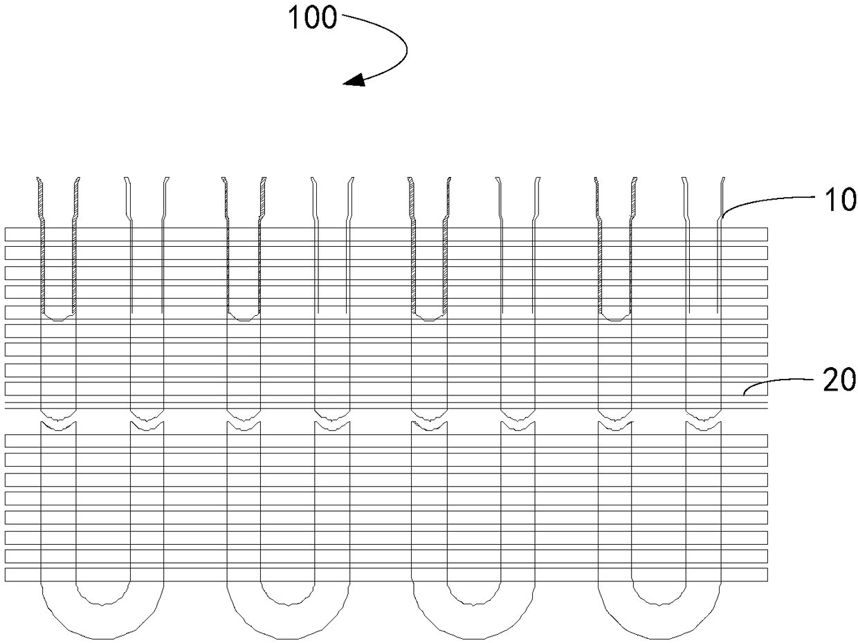
[0023] see figure 1 , The traditional heat exchanger 100 includes: a plurality of long U tubes 10 and a plurality of fins 20 connected in sequence. The fins 20 are in the shape of a sheet with a certain surface area, and may be in the shape of a square or other suitable irregular shapes (depending on the actual application environment). A plurality of fins 20 are arranged outside the long U-tube 10 at certain intervals to form a heat diss...


PUM


Abstract

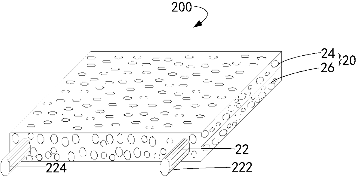
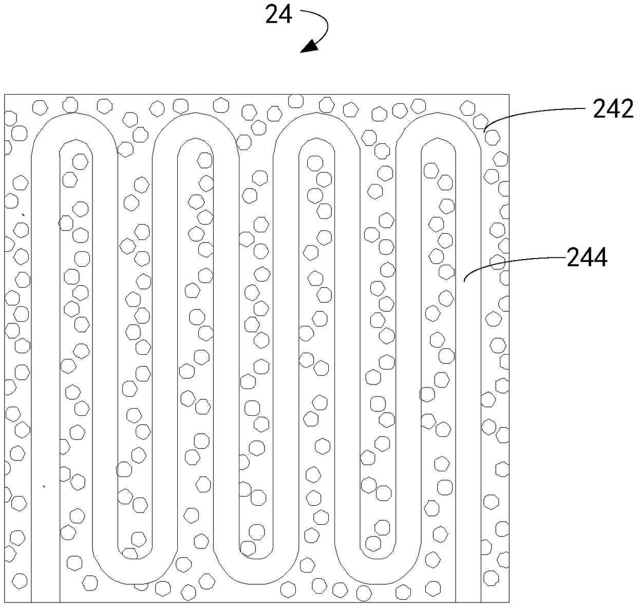
The invention relates to the technical field of heat exchangers, in particular to a heat exchanger and a making method thereof. The heat exchanger comprises foamed aluminum pieces and aluminum pipes which are installed in the foamed aluminum pieces. According to the heat exchanger provided by the embodiment, the heat exchanger is obtained in the combination manner of the foamed aluminum pieces andthe aluminum pipes; because the density of the aluminum pipes is smaller than that of copper pipes, the overall weight of the foamed aluminum pieces is smaller than the weight of aluminum fins, and thus, according to the heat exchanger formed by the foamed aluminum pieces and the aluminum pipes, the weight of the heat exchanger can be reduced easily. In addition, the overall self-corrosion potentials of the heat exchanger are close to each other, and it is avoided that because a large potential difference exists between the copper pipes and the aluminum fins of traditional heat exchangers, corrosion is serious; and secondly, the foamed aluminum structure increases the cooling area, the heat exchanging efficiency of the heat exchanger is greatly improved.

Description

technical field [0001] The invention relates to the technical field of heat exchangers, in particular to a heat exchanger and a manufacturing method thereof. Background technique [0002] At present, most of the heat exchangers of air conditioners and dehumidifiers are tube-fin structures with copper tubes and aluminum fins. Penetrate the fins, expand the inner diameter of the U-shaped copper tube with a tube expander, and after drying, insert an elbow to connect the U-shaped copper tube for welding to obtain a preliminarily formed heat exchanger. [0003] In the process of realizing the present invention, the inventor found that: on the one hand, using copper tubes as the refrigerant transmission channel, the overall mass of the heat exchanger will be relatively heavy; and other processes make the production process of the heat exchanger complicated. Therefore, the structure of the existing heat exchanger needs to be further improved. Contents of the invention [0004]...

Claims


Application Information

Patent Timeline
Patent Type & Authority Applications(China)
IPC IPC(8): F28D7/08F28F1/30F28F1/32F28F21/08
CPCF28D7/082F28F1/30F28F1/32F28F21/084
Inventor 李勉彭楚堂王琳王红霞马颖江熊佳龙
Owner GREE ELECTRIC APPLIANCES INC
Learn More