Eureka AIR delivers breakthrough ideas for toughest innovation challenges, trusted by R&D personnel around the world.

Heat storage method of impregnated sandstones and device thereof

A heat storage device, sand and gravel technology, applied in heat storage equipment, heat exchanger types, indirect heat exchangers, etc., can solve the problems of reduced working life of concrete heat storage equipment, reduced heat transfer performance of concrete, and damage to the overall structure , to achieve the effects of easy application, improved heat transfer performance, and extended operating life

Pending Publication Date: 2018-06-12
XIAN ZHONGYUAN MACHINERY CO LTD
View PDF0 Cites 0 Cited by
  • Summary
  • Abstract
  • Description
  • Claims
  • Application Information

AI Technical Summary

Problems solved by technology

However, the traditional concrete heat storage equipment and heat storage method, which use sand and gravel as the main heat storage material, and cement as the cementitious material to solidify the sand and gravel and the heat transfer medium pipeline, have the following disadvantages: (1) The cement gelled form The concrete is prone to dehydration at a high temperature above 400°C for a long time, causing destructive structural changes in the concrete structure and detachment of metal pipes, so that air will enter the gaps, greatly reducing the heat transfer performance of the concrete; (2) , and the rigid heat storage structure glued together with the metal pipes will generate thermal stress due to the difference in expansion coefficient. In the long-term alternating cold and heat environment, the metal pipes and concrete will also be separated, destroying the overall structure, and making the traditional Reduced working life of concrete heat storage equipment

Method used


Image

  • Heat storage method of impregnated sandstones and device thereof

Examples


Embodiment Construction

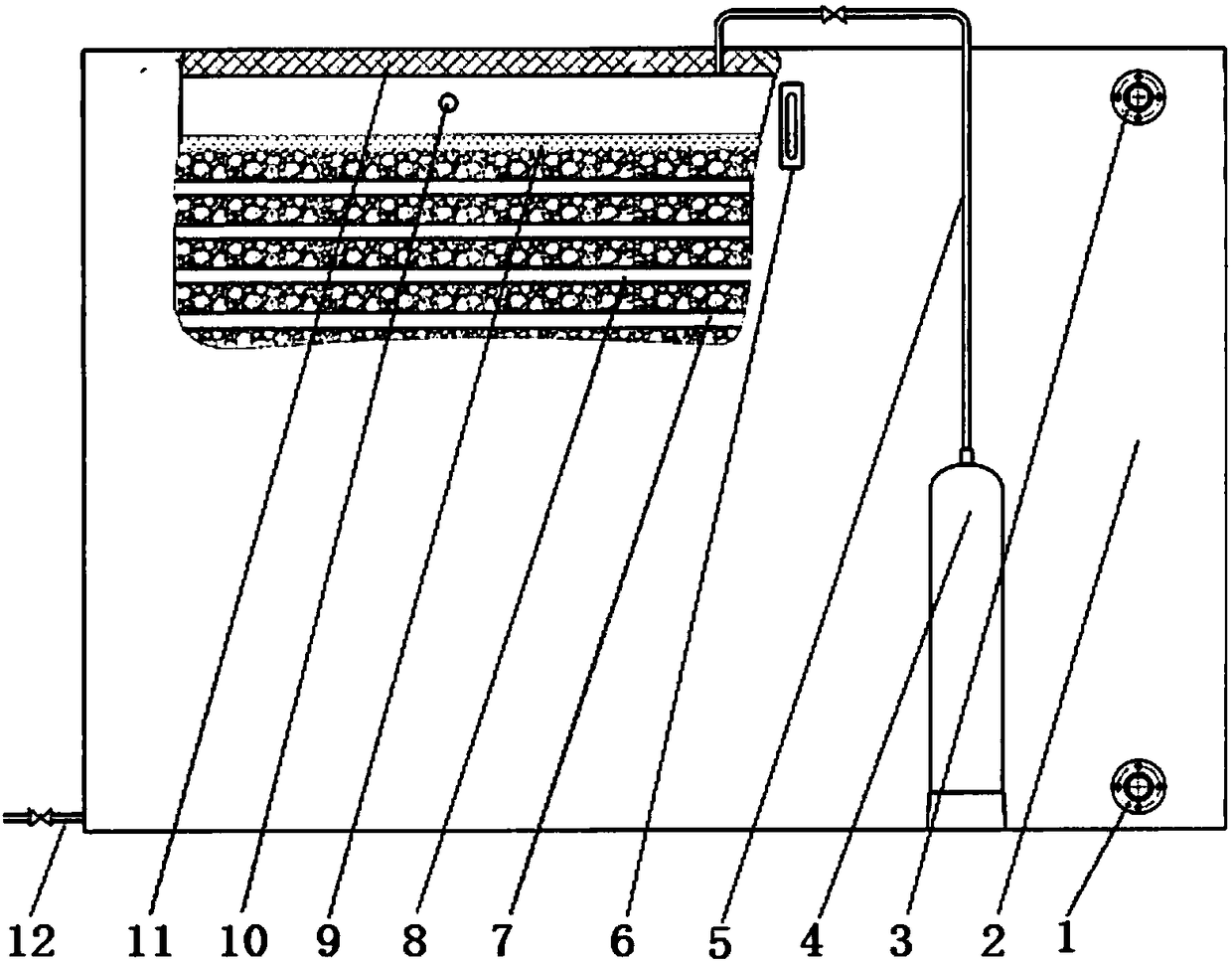
[0021] The heat storage method of impregnated sand and gravel in the present invention is as follows: a tube-rack heat exchanger is installed in the closed container of the heat storage system of the closed container, filled with sand and gravel, and then injected with an impregnating medium so that the liquid level of the impregnated medium is higher than that of the sand The fine gaps between the sand and gravel are filled in parallel to improve the heat storage performance of the sand and gravel, which can reduce the distribution density of the fluid pipeline in the heat storage device, reduce the resistance of the pipeline, reduce the power of the circulating pump, and reduce the cost of the heat storage project. come down. The heat storage method of impregnated sandstone in the present invention is divided into medium temperature heat storage and high temperature heat storage. The medium-temperature heat storage impregnation medium and heat transfer medium are both heat-c...


PUM


Abstract

The invention relates to a heat storage method of impregnated sandstones and a device thereof. According to the heat storage method, a closed container heat storage system in which a pipe frame type heat exchanger pipeline is arranged is filled with sandstones, and conduction oil or fused salt is injected into gaps between the sandstones, so that the sandstones and the pipe frame type heat exchanger pipeline are impregnated into the conduction oil or the fused salt. The heat storage device is provided with a closed container with an insulating layer, a pipe frame type heat exchanger is installed in the closed container, the closed container is filled with sandstones, impregnated media are injected into the gaps between the sandstones, a nitrogen cylinder is arranged outside the closed container, and an outlet of the nitrogen cylinder is introduced into the closed container through a nitrogen pipe. According to the heat storage method, the structure of the impregnated sandstones is adopted, so that the heat transfer performance of the heat storage device can be greatly improved, and the distribution density of heat transfer pipelines in the heat storage device and the power of a transfer pump are reduced. The heat storage method has the advantages of reasonable design scheme and easiness in implementation and application, and the heat storage construction cost can be greatly reduced in the condition that the heat storage requirements are satisfied.

Description

technical field [0001] The content of the present invention belongs to the technical field of heat storage, and relates to a heat storage method and device thereof by impregnating sand. Background technique [0002] In the field of heat storage technology, using cheap and easy-to-obtain sand and stone as heat storage materials has always been the pursuit goal of relevant scientific and technological workers. However, the traditional concrete heat storage equipment and heat storage method, which use sand and gravel as the main heat storage material, and cement as the cementitious material to solidify the sand and gravel and the heat transfer medium pipeline, have the following disadvantages: (1) The cement gelled form The concrete is prone to dehydration at a high temperature above 400°C for a long time, causing destructive structural changes in the concrete structure and detachment of metal pipes, so that air will enter the gaps, greatly reducing the heat transfer performanc...

Claims


Application Information

Patent Timeline
Patent Type & Authority Applications(China)
IPC IPC(8): F28D20/00
CPCF28D20/00Y02E60/14
Inventor 刘绍允陶于兵何晓建何晓刚
Owner XIAN ZHONGYUAN MACHINERY CO LTD
Why Eureka
Eureka Blog
Learn More