
Method for analyzing pipeline depositing distribution

A pipeline and sediment technology, applied in the field of pipeline inspection, can solve problems such as complex operation process, threat to staff safety and health, expensive equipment, etc.

Pending Publication Date: 2018-06-12
上海水顿智能科技有限公司
View PDF6 Cites 12 Cited by
  • Summary
  • Abstract
  • Description
  • Claims
  • Application Information

AI Technical Summary

Problems solved by technology

[0004] The disadvantage of the above-mentioned manual inspection method is that the situation in the drainage pipe is complicated, and there is a certain concentration of toxic and harmful gases, which may pose a threat to the safety and health of the staff; the disadvantage of CCTV detection is that the equipment is expensive, the operation process is relatively complicated, and the inspection process affects Pipe network operation
At present, there is a lack of a simple and effective technical means to grasp the actual operation status of the drainage pipe network in terms of operation and management, so as to evaluate the daily sedimentation of the underground drainage pipe network and provide necessary data support for the hydraulic analysis and maintenance and dredging management of the drainage pipe network.

Method used


Image

  • Method for analyzing pipeline depositing distribution
  • Method for analyzing pipeline depositing distribution
  • Method for analyzing pipeline depositing distribution

Examples


Embodiment Construction

[0055] Below in conjunction with specific embodiment, further illustrate the present invention. It should be understood that these examples are only used to illustrate the present invention, not to limit the protection scope of the present invention. Improvements and adjustments made by those skilled in the art according to the present invention in practical applications still belong to the protection scope of the present invention.

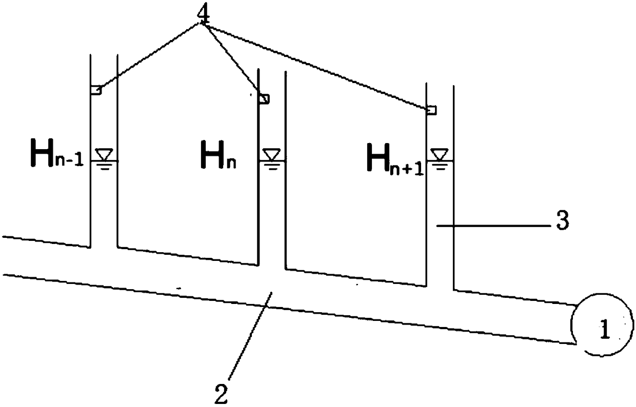
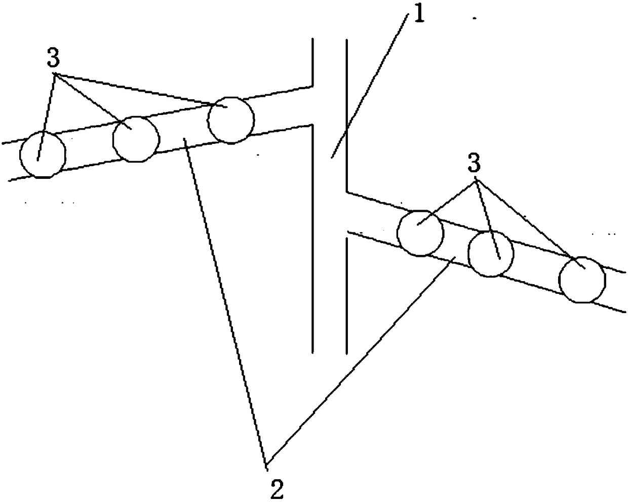
[0056] In order to better illustrate the present invention, the present invention will be described in detail below in conjunction with the accompanying drawings.

[0057] A method for analyzing the distribution of pipeline silt, comprising the steps of:

[0058] S1: Obtain the parameters of each drainage pipe, including pipe length, pipe diameter, pipe slope, and roughness coefficient; conduct pipe grouping, including grouping several pipes in the drainage system that are connected end to end, have the same pipe diameter, and have no change in ...


PUM


Abstract

The invention discloses a method for analyzing pipeline depositing distribution. The method includes: S1, acquiring parameters of each drainage pipeline, grouping the pipelines, and mounting a liquidlevel meter at an inspection well upstream or downstream of each pipeline; S2, screening and processing water level data to acquire water level Hn of the inspection well; S3, performing following hydraulic calculation according to whether water flow state in each pipeline is a full-flow pipe or a non-full-flow pipe; S31, for the full-flow pipe, judging depositing condition according to relative difference between hn local and hn frictional, wherein water level difference delta H is mainly composed of local head loss h local and frictional head loss h frictional; S32, for the non-full-flow pipe, adopting Froude number Fr of water flow and water flow velocity v to judge depositing condition. The liquid level meter or a flow meter is mounted in the inspection well to screen, process and analytically calculate acquired water level or flow data, real-time tracking and monitoring of depositing distribution of the drainage pipelines are realized in a more economical and safer manner, and a related basis is provided for desilting period of the drainage pipelines.

Description

technical field [0001] The invention belongs to the field of pipeline detection, in particular to a method for analyzing pipeline silt distribution. Background technique [0002] The sewage is collected and discharged to the treatment facilities through the drainage pipes, but the suspended solids in the sewage will settle during the transportation process; with the increase of the service time of the drainage pipes, the possibility of sedimentation increases sharply. important issues facing. Sediment accumulation hydraulically will cause increased head loss along the way, resulting in poor drainage, resulting in overloading of the drainage system and premature arrival of combined overflow, and even overflowing the road surface, causing water accumulation and environmental pollution. [0003] At present, the common methods for judging the distribution of drainage pipe silting are manual investigation and CCTV detection (television detection of drainage pipe). For large-dia...

Claims


Application Information

Patent Timeline
Patent Type & Authority Applications(China)
IPC IPC(8): G01D21/00
CPCG01D21/00
Inventor 余十平梁怿祯谢予婕顾强黄天翔蒋玲玲陈林马仁海肖伟民祝敏刘广
Owner 上海水顿智能科技有限公司
Learn More