
A wheel detection device

A detection device and wheel technology, applied in wheel testing and other directions, can solve the problems of wheel smashing and injury to workers, heavy wheel weight, time-consuming and labor-intensive, etc., and achieve the effect of protecting wheels, reducing energy consumption, and ensuring detection results.

Active Publication Date: 2019-11-08
齐河智谷产业发展有限公司
View PDF7 Cites 0 Cited by
  • Summary
  • Abstract
  • Description
  • Claims
  • Application Information

AI Technical Summary

Problems solved by technology

Due to the heavy weight of the wheels, on the one hand, it is time-consuming and labor-intensive during the manual handling process, and it is inconvenient to operate. On the other hand, the wheels are easy to fall from the machine during the inspection process and injure the workers, causing potential safety hazards.

Method used


Image

  • A wheel detection device
  • A wheel detection device

Examples


Embodiment Construction

[0015] The present invention will be described in further detail below by means of specific embodiments:

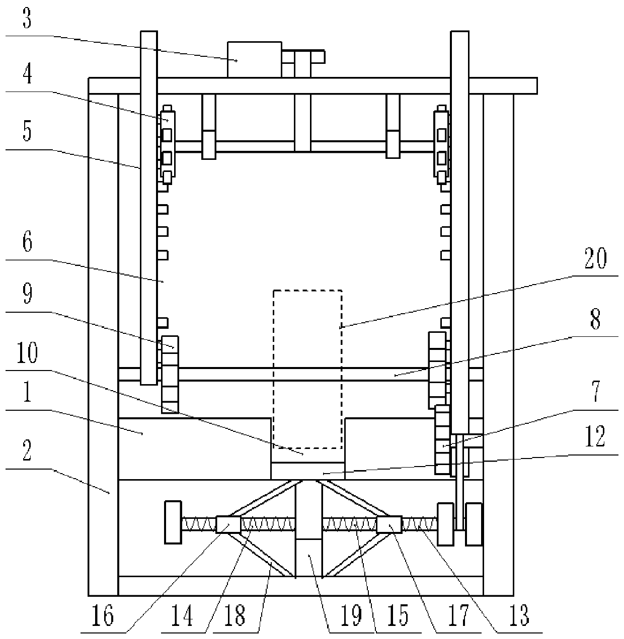
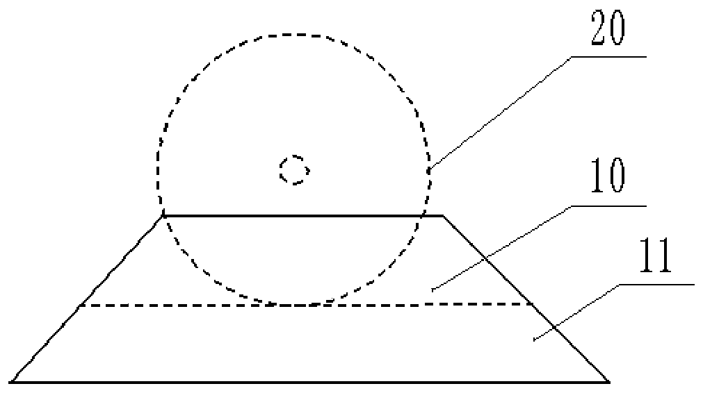
[0016] The reference signs in the drawings of the description include: machine 1, frame 2, motor 3, lifting gear 4, rack 5, notch 6, transmission gear 7, horizontal shaft 8, turning gear 9, positioning groove 10, inclined rail 11. Bottom plate 12, threaded rod 13, first threaded part 14, second threaded part 15, first sliding sleeve 16, second sliding sleeve 17, first inclined arm 18, support column 19, wheel 20.

[0017] The embodiment is basically as figure 1 Shown: a wheel detection device, including a machine 1, a frame 2 is provided on the machine 1, a motor 3 and two sets of first lifting mechanisms are arranged on the frame 2, and the two sets of first lifting mechanisms are respectively located on the frame 2 left and right. The first lifting mechanism includes a meshing lifting gear 4 and a rack 5. A gear shaft is welded and fixed between the two lifting gears ...


PUM


Abstract

The invention relates to the technical field of wheel detection equipment, and discloses a wheel detection device. The device comprises a machine bench. A machine frame is arranged on the machine bench. A motor and a first lifting mechanism are arranged on the machine frame. The first lifting mechanism comprises a lifting gear and a rack, wherein the lifting gear and the rack are meshed with eachother. The lifting gear is in belt connection with the power shaft of the motor. The rack is connected onto the machine frame in a sliding mode. A transmission gear is further meshed with the rack. Asliding chute is formed in the rack. A transverse shaft is detachably connected to the machine frame. The transverse shaft penetrates through the sliding chute to be arranged. The two ends of the transverse shaft are connected to the machine frame in a sliding mode, and the machine bench is located right below the transverse shaft. A machining station is arranged on the machine bench. The machining station is connected with an inclined rail connected with the ground. The machining station comprises a movably connected bottom plate. The bottom plate is connected with a second lifting mechanism,and the second lifting mechanism comprises a shaft rod. The shaft rod is located between the bottom plate and the bottom of the machine frame. The shaft rod is in belt connection with the transmission gear. According to the invention, wheels can be conveniently carried and detected. The labor intensity of workers is reduced, and the occurrence of potential safety hazards is also reduced.

Description

technical field [0001] The invention relates to the technical field of wheel detection equipment, in particular to a wheel detection device. Background technique [0002] In order to ensure the normal running of the car, it is often necessary to detect the performance of the wheels. When testing the wheels in the prior art, it is necessary to manually transport the wheels to the machine platform, and then use testing equipment to test the wheels. Due to the heavy weight of the wheels, on the one hand, it is time-consuming and labor-intensive during manual handling, and it is inconvenient to operate. On the other hand, the wheels are also easy to fall from the machine during the inspection process and injure workers, causing potential safety hazards. Contents of the invention [0003] The present invention intends to provide a wheel detection device, so as to facilitate the handling and detection of the wheels, reduce the labor intensity of workers, and reduce potential sa...

Claims


Application Information

Patent Timeline
Patent Type & Authority Patents(China)
IPC IPC(8): G01M17/013
CPCG01M17/013
Inventor 卢加权
Owner 齐河智谷产业发展有限公司
Learn More