Adjustable clamp for high-speed friction and and wear testing machine

A friction and wear test and adjustable technology, applied in the field of machinery, can solve the problems that the fixture cannot be translated, and the friction and wear test clamping of machining tools cannot be realized, so as to avoid singleness, ensure the clamping accuracy, and improve the positioning accuracy. Effect

Inactive Publication Date: 2018-06-12
HARBIN UNIV OF SCI & TECH
View PDF4 Cites 3 Cited by
  • Summary
  • Abstract
  • Description
  • Claims
  • Application Information

AI Technical Summary

Problems solved by technology

[0005] In order to solve the problem that the existing friction and wear testing machine fixtures cannot realize translation, and can not realize the friction and wear test clamping of machining tools at any angle, the present invention further proposes an adjustable high-speed friction and wear testing machine.

Method used


Image

  • Adjustable clamp for high-speed friction and and wear testing machine
  • Adjustable clamp for high-speed friction and and wear testing machine
  • Adjustable clamp for high-speed friction and and wear testing machine

Examples


specific Embodiment approach 1

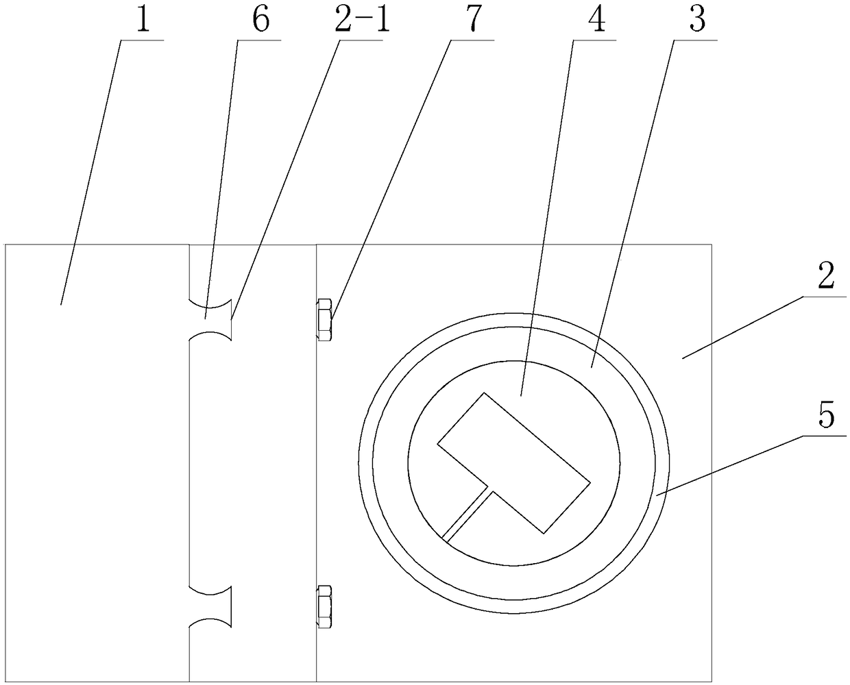
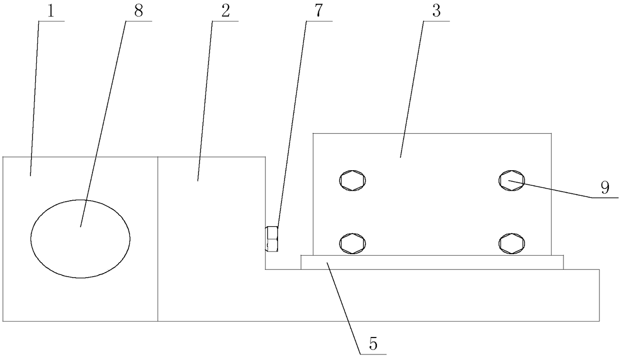
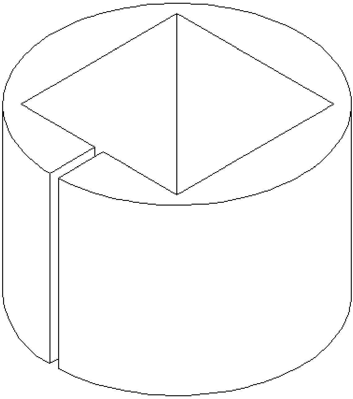
[0019] Specific implementation mode one: combine figure 1 with figure 2 Describe this embodiment, a kind of adjustable high-speed friction and wear testing machine fixture described in this embodiment includes connecting block 1, mobile platform 2, fixture sleeve 3 and friction style sleeve 4, the connecting block 1 and mobile platform 2 One end is connected, the clamp sleeve 3 is installed vertically on the mobile platform 2 , and the friction pattern sleeve 4 is inserted in the clamp sleeve 3 .

specific Embodiment approach 2

[0020] Specific implementation mode two: combination figure 1 with figure 2 To illustrate this embodiment, the mobile platform 2 of the fixture for an adjustable high-speed friction and wear testing machine described in this embodiment is provided with a fixture sleeve positioning boss 5, and the fixture sleeve 3 is installed on the fixture sleeve positioning boss 5 Above, at least one fixing bolt 9 for fixing the friction pattern sleeve 4 is provided on the outer wall of the clamp sleeve 3 . Other components and connections are the same as those in the first embodiment.

specific Embodiment approach 3

[0021] Specific implementation mode three: combination figure 1 with figure 2 Describe this embodiment, the connection block 1 of the clamp for an adjustable high-speed friction and wear testing machine described in this embodiment is connected with the mobile platform 2, and two guide rails 6 are arranged side by side in parallel. One end face is provided with two slide grooves 2-1 matched with the guide rails 6, and the two guide rails 6 are respectively inserted into the two slide grooves 2-1. Other components and connections are the same as those in the first embodiment.


PUM


Abstract

The invention provides an adjustable clamp for a high-speed friction and wear testing machine, relates to a clamp for a wear testing machine, and particularly relates to an adjustable clamp for the ahigh-speed friction and wear testing machine. The invention aims to solve the problems that an existing clamp for thea friction and wear testing machine can not realize horizontal movement and can notrealize friction and wear test clamping of a machining cutter at any angle. The clamp provided by the invention comprises a connecting block, a mobile station, a clamp sleeve and a friction model sleeve, wherein the connecting block is connected with one end of the mobile station, the clamp sleeve is vertically mounted on the mobile station, and the friction model sleeve is inserted in the clampsleeve. The clamp provided by the invention belongs to the field of machinery.

Description

technical field [0001] The invention relates to a fixture for an abrasion testing machine, in particular to an adjustable fixture for a high-speed friction and wear testing machine, belonging to the field of machinery. Background technique [0002] There is friction in the relative movement between mechanical parts, and this contact friction will cause serious wear of mechanical parts during normal operation, thus reducing the service life of mechanical equipment. In the machining industry, when processing some difficult-to-machine materials, tool wear is also the main form of tool failure. Therefore, in order to improve the service life of mechanical parts and processing tools and reduce wear, it is necessary to conduct in-depth research on the friction and wear mechanism and the tribological properties of materials. [0003] With the development of science and technology, tribology testing and analysis technology develops very rapidly. More and more advanced technologies...

Claims


Application Information

Patent Timeline
Patent Type & Authority Applications(China)
IPC IPC(8): G01N3/04
CPCG01N3/04
Inventor 杨树财何春生郑敏利张玉华万泉
Owner HARBIN UNIV OF SCI & TECH
Why Eureka
Try Eureka