A Synchronous Hybrid Delay Type DPWM Module Based on FPGA

A delay chain, synchronous circuit technology, applied in the direction of pulse duration/width modulation, etc., can solve the problem of limited counter operating frequency delay chain high circuit resource occupancy, difficult to achieve high precision, digital pulse width modulator limited Sampling delay and resolution, etc., to achieve the effect of high production cost, guaranteed accuracy, and high linearity

Active Publication Date: 2021-05-04
HEFEI UNIV OF TECH
View PDF5 Cites 0 Cited by
  • Summary
  • Abstract
  • Description
  • Claims
  • Application Information

AI Technical Summary

Problems solved by technology

[0002] Digital pulse width modulators (DPWM) have been developed for a long time. Traditional digital pulse width modulators are limited by sampling delay and resolution. At the same time, traditional digital pulse width modulators use a single counter delay or A single delay chain delay is implemented. These single structures are limited by the operating frequency of the counter and the high circuit resource occupancy rate of the delay chain, and it is difficult to achieve high precision within limited design indicators.

Method used


Image

  • A Synchronous Hybrid Delay Type DPWM Module Based on FPGA
  • A Synchronous Hybrid Delay Type DPWM Module Based on FPGA
  • A Synchronous Hybrid Delay Type DPWM Module Based on FPGA

Examples


Embodiment Construction

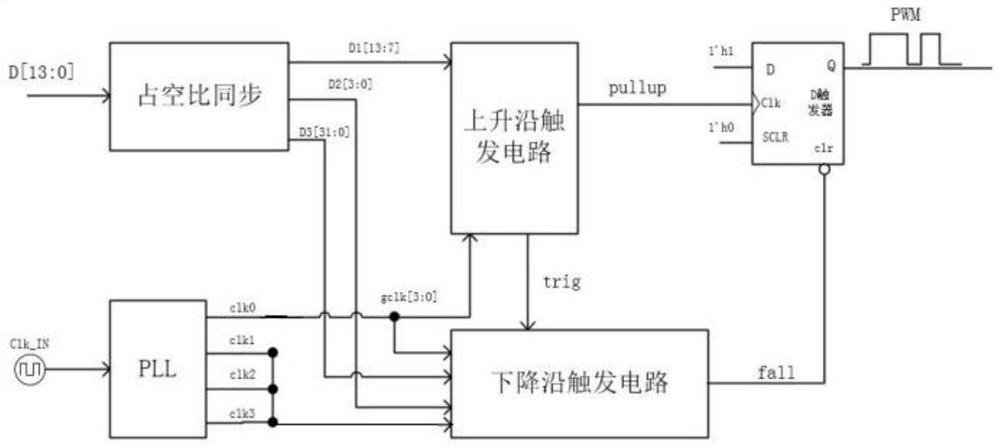
[0032] In this embodiment, the 14-bit DPWM structure is taken as an example (but not limited to 14 bits). An FPGA-based synchronous hybrid delay chain type DPWM module includes: rising edge trigger circuit, falling edge trigger circuit, duty cycle synchronous decoding circuit, register and phase-locked loop clock generation circuit;

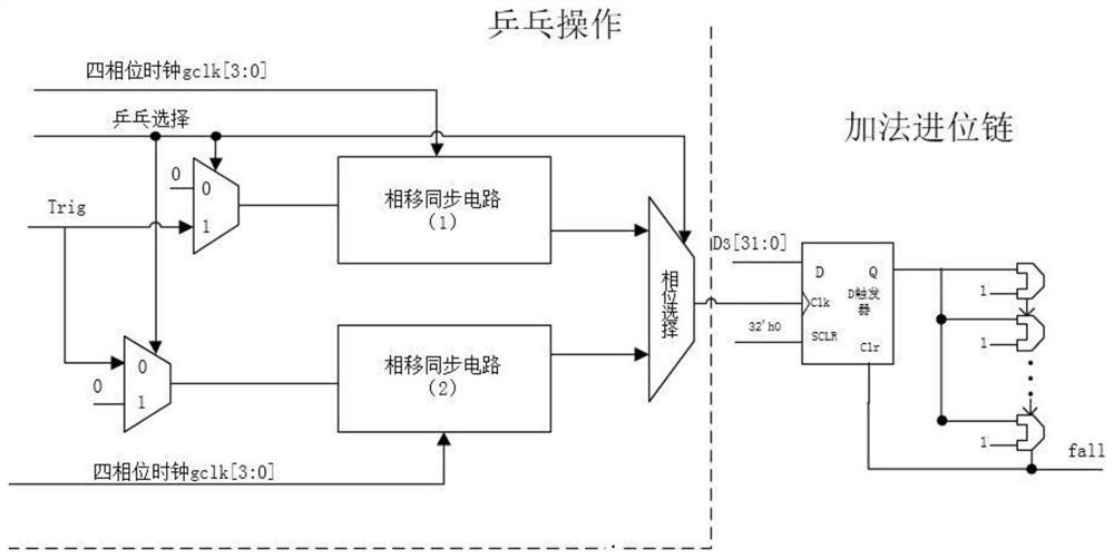
[0033] The falling edge trigger circuit includes: two phase shift synchronous circuits, an addition and carry chain reset signal generation circuit;

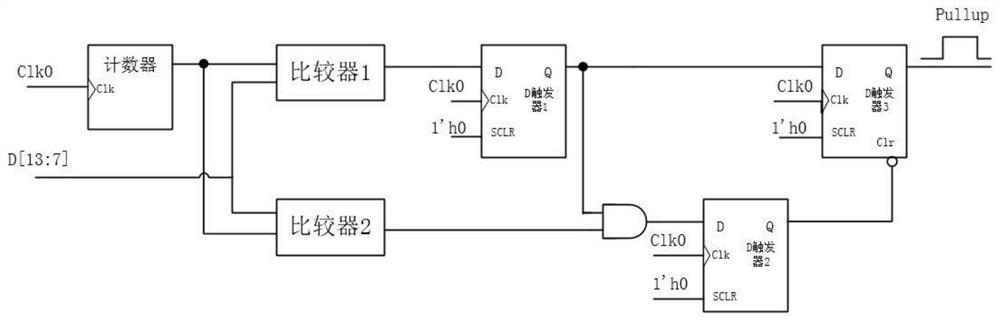
[0034] The duty cycle synchronous decoding circuit obtains the n-bit duty cycle signal and performs segmentation processing, and converts the n-bit to the m-bit duty cycle signal D in the n-bit duty cycle signal 1 [n-1:m-1] is sent to the rising edge trigger circuit, and the duty cycle signal D from the m-1th to the m-2th bit 2 [m-2:m-3] After decoding, the four-digit digital signal D is obtained 2 [3:0] is sent to the falling edge trigger circuit, and the duty ratio signal D from the m-3 bit to ...


PUM


Abstract

The invention discloses a synchronous hybrid delay type DPWM structure based on FPGA, and its submodules include: a rising edge trigger circuit based on a counter, a synchronous clock generation module based on a PLL (phase-locked loop), and a falling edge trigger circuit based on The pulse width modulation wave output module of the register, and the duty cycle synchronous decoding module. The invention can improve the time resolution of the pulse width modulator and the linearity and stability of the duty cycle, thereby reducing the ripple and stabilization time of the DC-DC converter, suppressing and weakening the overshoot and ringing that occur in the modulation process, At the same time, the mixed structure of the counter and the delay chain of the present invention can avoid the disadvantages of frequency limitation and excessive resource occupation of a single structure, expand the working frequency range of DPWM, and reduce the resources occupied by the circuit.

Description

technical field [0001] The invention relates to the field of power management chips, in particular to a DPWM module used in power management control circuits. Background technique [0002] Digital pulse width modulators (DPWM) have been developed for a long time. Traditional digital pulse width modulators are limited by sampling delay and resolution. At the same time, traditional digital pulse width modulators use a single counter delay or A single delay chain delay is implemented. These single structures are limited by the operating frequency of the counter and the high circuit resource occupancy of the delay chain, and it is difficult to achieve high precision within limited design indicators. Therefore, optimizing the structure of DPWM, reducing the circuit resources used in the design, increasing the operating frequency, improving the linearity, resolution and stability of DPWM are major challenges for current digital pulse width modulators. Contents of the invention ...

Claims


Application Information

Patent Timeline
Patent Type & Authority Patents(China)
IPC IPC(8): H03K7/08
CPCH03K7/08
Inventor 程心许立新高翔
Owner HEFEI UNIV OF TECH
Why Eureka
Try Eureka