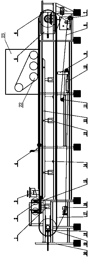
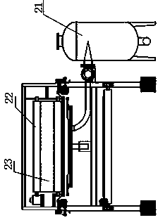
A steel belt vacuum press filter

A filter and vacuum technology, used in filtration and separation, moving filter element filters, separation methods, etc., can solve the problems of rapid wear and tear of rubber belts, affecting equipment life, etc., to reduce moisture content, reduce consumption, and increase service life. and the effect of continuous running time

Active Publication Date: 2020-06-05
NUCLEAR IND YANTAI TONCIN IND GRP CO LTD
View PDF6 Cites 0 Cited by
  • Summary
  • Abstract
  • Description
  • Claims
  • Application Information

AI Technical Summary

Problems solved by technology

[0003] The rubber belt and the grid plate on the rubber belt are indispensable and important parts in the rubber belt vacuum filter. However, since the rubber

Method used


Image

  • A steel belt vacuum press filter
  • A steel belt vacuum press filter
  • A steel belt vacuum press filter

Examples


Embodiment Construction

[0019] The present invention will be further described below in conjunction with the accompanying drawings and embodiments. Apparently, the described embodiments are some, but not all, embodiments of the present invention. Based on the embodiments of the present invention, all other embodiments obtained by persons of ordinary skill in the art without making creative efforts belong to the protection scope of the present invention.

[0020] In the description of the present invention, it should be noted that the terms "center", "upper", "lower", "left", "right", "vertical", "horizontal", "inner", "outer" etc. The indicated orientation or positional relationship is based on the orientation or positional relationship shown in the drawings, and is only for the convenience of describing the present invention and simplifying the description, rather than indicating or implying that the referred device or element must have a specific orientation, or in a specific orientation. construc...


PUM


Abstract

The invention discloses a steel belt type vacuum pressing filtering machine. The steel belt type vacuum pressing filtering machine comprises a machine frame, and a driving roller and a driven roller pivotally arranged at two ends of the machine frame, a decelerating motor drives the driving roller to rotate, a metal braided mesh conveyor belt is wound around the driving roller and the driven roller, the metal wire of the metal braided mesh conveyor belt is braided to form uniform arched protrusions at the outside and is flat at the inside, and the two side edges of the metal braided mesh conveyor belt are wrapped and sealed by elastic steel sheet strips; the horizontal section of a filter cloth is attached to the metal braided mesh conveyor belt and runs along with the progress of the metal braided mesh conveyor belt, a vacuum chamber is arranged on the machine frame and corresponding to the lower surface of the upper layer metal braided mesh conveyor belt, and the vacuum chamber is supported by two or more first hydraulic cylinders fixedly arranged on the machine frame, the vacuum chamber and the vacuum balance automatic liquid drainage tank communicate through a pipeline; and a pressing device is arranged above the filter cloth and at the position corresponding to the back section of the vacuum chamber. According to the steel belt type vacuum pressing filtering machine, the structure is simplified, lifespan is increased, operating noise is reduced, water content of a filter cake is reduced, and filtering effect is improved.

Description


Claims


Application Information

Patent Timeline
Owner NUCLEAR IND YANTAI TONCIN IND GRP CO LTD
Why Eureka
Try Eureka