Reactor with thin-wall lining and production method of reactor

A reactor and lining technology, which is applied in thin-walled reactors and its manufacturing field, can solve problems such as bulging and leakage, and achieve the effects of convenient socketing, reducing the number, and increasing sealing

Active Publication Date: 2018-06-15
HEFEI GENERAL MACHINERY RES INST +1
View PDF4 Cites 2 Cited by
  • Summary
  • Abstract
  • Description
  • Claims
  • Application Information

AI Technical Summary

Problems solved by technology

[0004] In order to overcome the deficiencies of the above-mentioned prior art, the purpose of the present invention is to solve the failure problems such as bulges and leaks that are prone to occur in the prior art under severe working conditions such as vacuum-medium pressure, cryogenic-high temperature, etc., for this reason , the invention provides a thin-walled liner reactor and its manufacturing method

Method used


Image

  • Reactor with thin-wall lining and production method of reactor
  • Reactor with thin-wall lining and production method of reactor
  • Reactor with thin-wall lining and production method of reactor

Examples


Embodiment 1

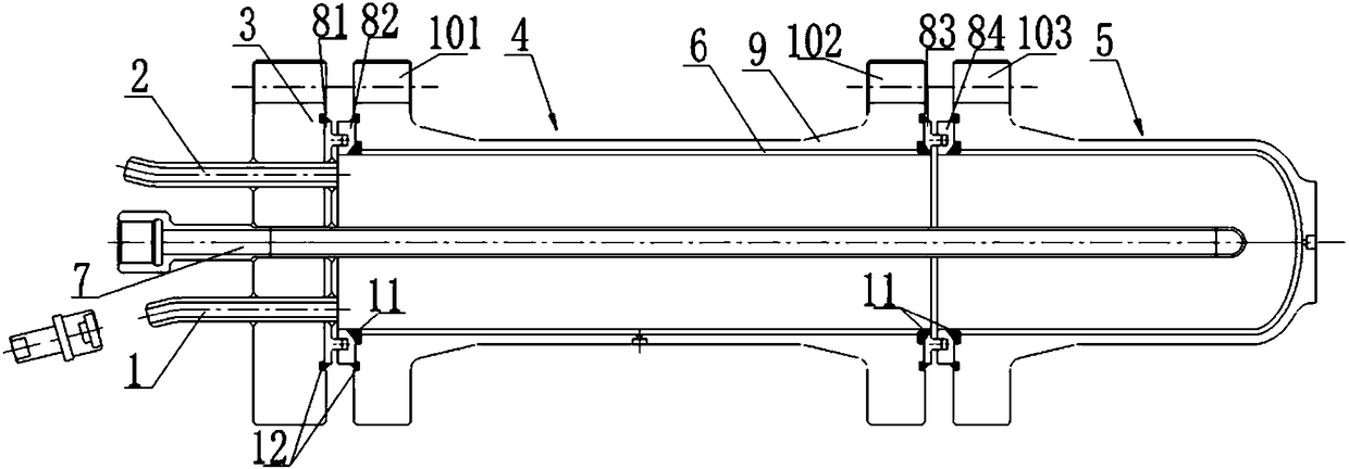
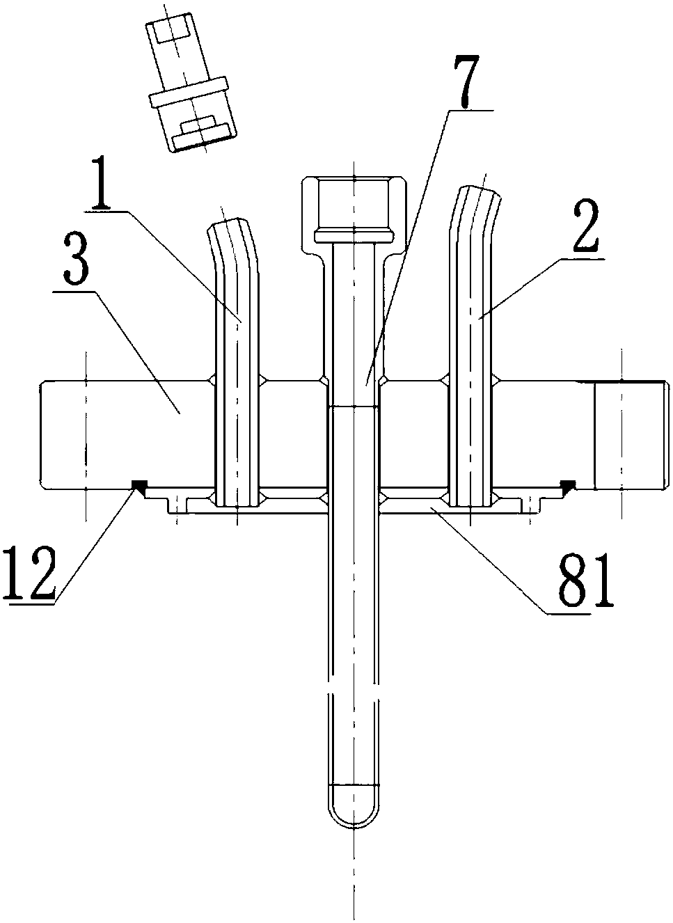
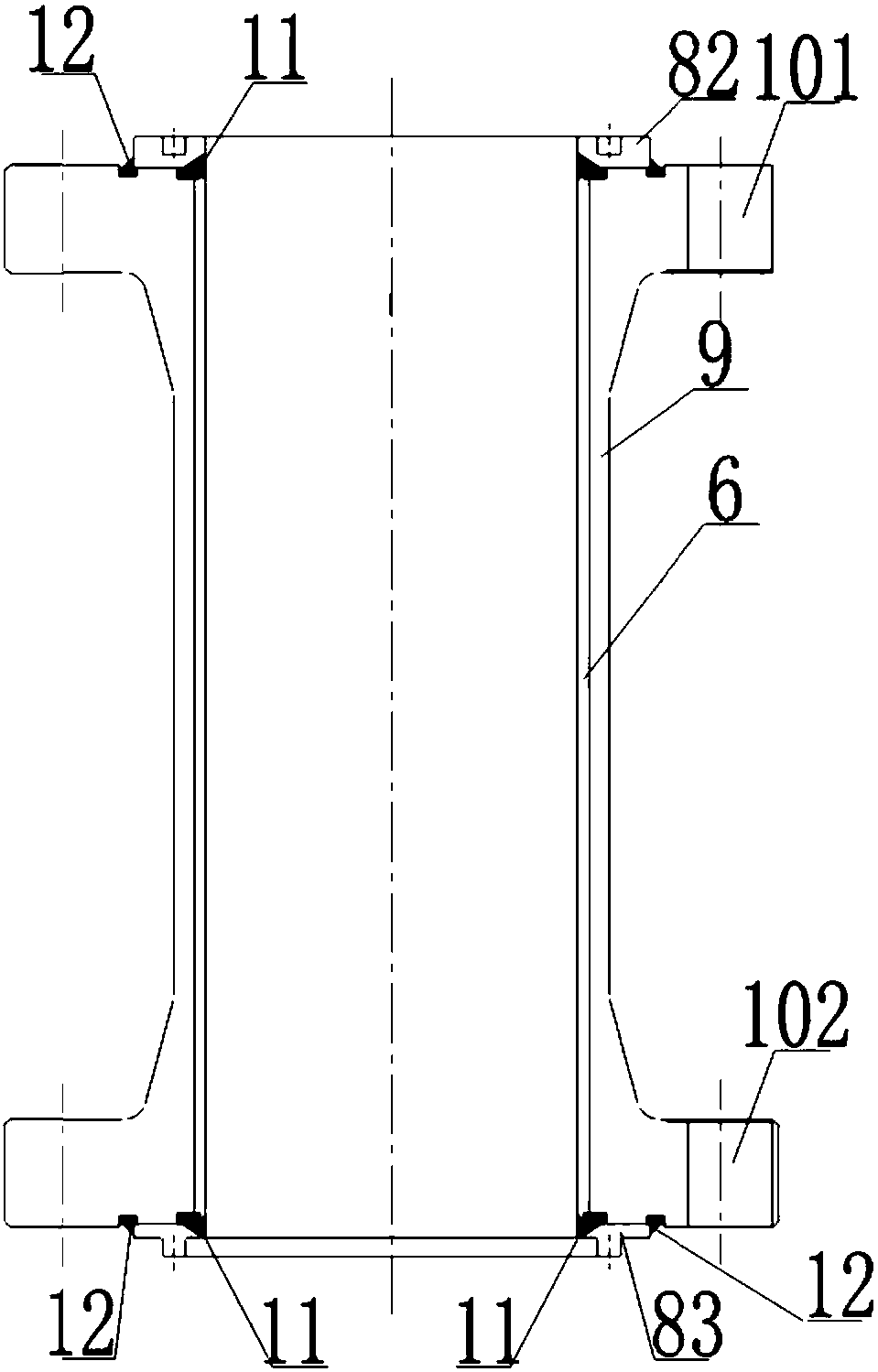
[0057] Such as Figure 1-4 As shown, a thin-walled lined reactor includes a flange cover 3, an upper shell 4 and a lower shell 5 fixedly connected in sequence, and the upper shell 4 and the lower shell 5 both include inner layers connected to each other through a heat sleeve The cylinder 6 and the outer cylinder 9, the flange cover 3 is provided with a material inlet 2, a material outlet 1 and a test insertion port 7, the inner cylinder 6 of the upper shell 4, and the inner cylinder of the lower shell 5 6. The flange cover 3 and the material inlet 2, the material outlet 1, and the test insertion port 7 on the flange cover 3 form a sealed reaction chamber. In this embodiment, the test insertion port 7 is sealed with a downward housing 5-direction extended temperature test device.

[0058] Both the inner cylinder body 6 and the outer cylinder body 9 of the lower shell 5 are composed of a straight cylinder section and a lower head. The straight section of the cylinder 9 and the...

Embodiment 2

[0072] A kind of thin-wall lining reactor of manufacturing embodiment 1, comprises the steps:

[0073] S1. Determine the set dimensions of the outer cylinder body 9 and the inner cylinder body 6 after processing, and the outer diameter of the material used is greater than the set dimensions of the outer diameter of the outer cylinder body 9 and the outer diameter of the inner cylinder body 6 , the inner diameter is smaller than the set size of the inner diameter of the outer cylinder 9 and the inner diameter of the inner cylinder 6, and the length is greater than the set size of the length of the straight section of the outer cylinder 9 and the length of the straight section of the inner cylinder 6, and the inner The length of the layer cylinder body 6 is greater than the length of the outer layer cylinder body 9, and the outer layer cylinder body 9 and the inner layer cylinder body 6 are processed;

[0074] Wherein the specific size of the outer shell 9 and the inner shell 6 ...


PUM


Abstract

The invention discloses a reactor with a thin-wall lining and a production method of the reactor. The reactor with the thin-wall lining comprises a blind flange, an upper shell and a lower shell whichare fixedly connected in sequence; each of the upper shell and the lower shell comprises an inner-layer cylinder and an outer-layer cylinder which are connected by a hot jacket; a material inlet, a material outlet and a test insertion hole are formed in the blind flange; and the inner-layer cylinder of the upper shell, the inner-layer cylinder of the lower shell, the blind flange as well as the material inlet, the material outlet and the test insertion hole in the blind flange form a sealed reaction cavity. The reactor has the advantages that the inner-layer cylinder and the outer-layer cylinder are connected by a hot jacket structure, so that the invalidation problem that a reactor produced in the prior art is easy to swell and leak can be effectively avoided under the condition that thesize is suited; and due to the arrangement of the upper shell and the lower shell, cup joint is conveniently realized.

Description

technical field [0001] The invention relates to the field of reactors, in particular to a thin-wall lined reactor and a manufacturing method thereof. Background technique [0002] In the industrial fields of metallurgy, nuclear energy, chemical industry and medicine, in order to obtain high-purity materials, it is necessary to separate, purify or concentrate the reaction materials. The reaction process is often accompanied by a large temperature difference and high variable stress from low temperature to high temperature and pressure from vacuum to medium and high pressure. At the same time, the reaction materials exhibit different material states at different temperatures, or are highly corrosive, or have extremely high requirements for material purity and cleanliness. For this reason, it is necessary to ensure the safety of equipment strength under low temperature or high temperature and high pressure environment, and to ensure that the materials in contact with materials ...

Claims


Application Information

Patent Timeline
Patent Type & Authority Applications(China)
IPC IPC(8): B01J19/02
CPCB01J19/0053B01J19/02B01J2219/0277
Inventor 徐鹏程窦万波周挺贺学志吴磊崔军汪兵傅逸芳刘志张义军王勇
Owner HEFEI GENERAL MACHINERY RES INST
Why Eureka
Try Eureka