
An automatic embossing device

An embossing and movable end technology, applied in the field of automatic embossing devices, can solve the problems of concave conveyor belt, time-consuming and labor-intensive, affecting processing operations, etc., and achieve the effects of improving accuracy, convenient use and compact structure

Inactive Publication Date: 2020-05-22
嘉善翱鹰五金制品厂
View PDF4 Cites 0 Cited by
  • Summary
  • Abstract
  • Description
  • Claims
  • Application Information

AI Technical Summary

Problems solved by technology

[0002] In the process of mechanical production and processing, it is often necessary to emboss the accessories. The traditional method is to place the accessories on the flattening workbench for flattening, and then transfer them to the embossing workbench for embossing. The operation is cumbersome. Time-consuming
There are also devices on the market that transport accessories to the embossing motor or flattening motor through conveyor belts for processing. However, most of these devices have complex structures, large volumes and high costs, and it is difficult to accurately control the distance of accessories transportation.
At the same time, when processing operations on the conveyor belt, it is easy to cause the conveyor belt to sag due to the processing force, which not only easily damages the conveyor belt, but also affects normal processing operations

Method used


Image

  • An automatic embossing device
  • An automatic embossing device

Examples


Embodiment Construction

[0021] In order to make the technical means, creative features, goals and effects achieved by the present invention easy to understand, the present invention will be further described below in conjunction with specific embodiments.

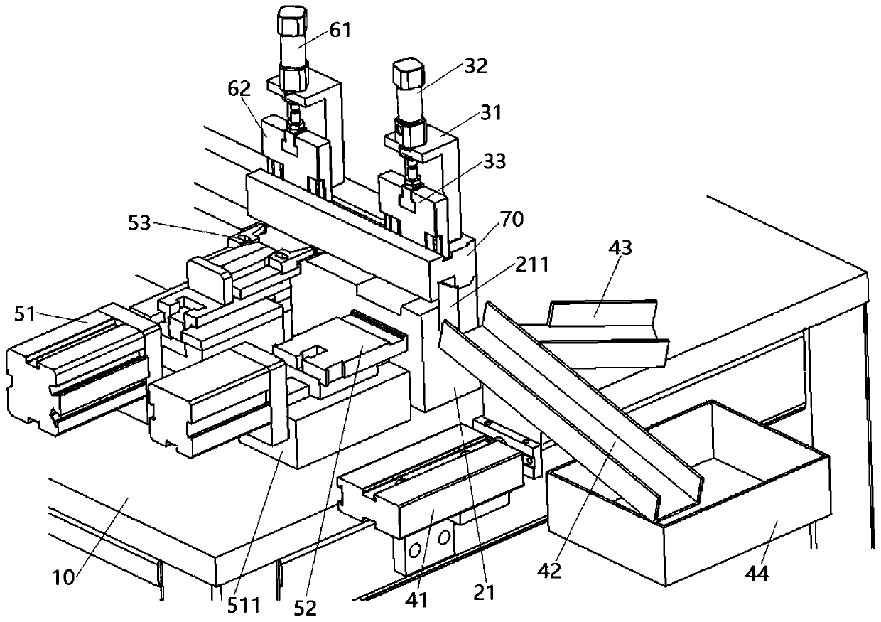
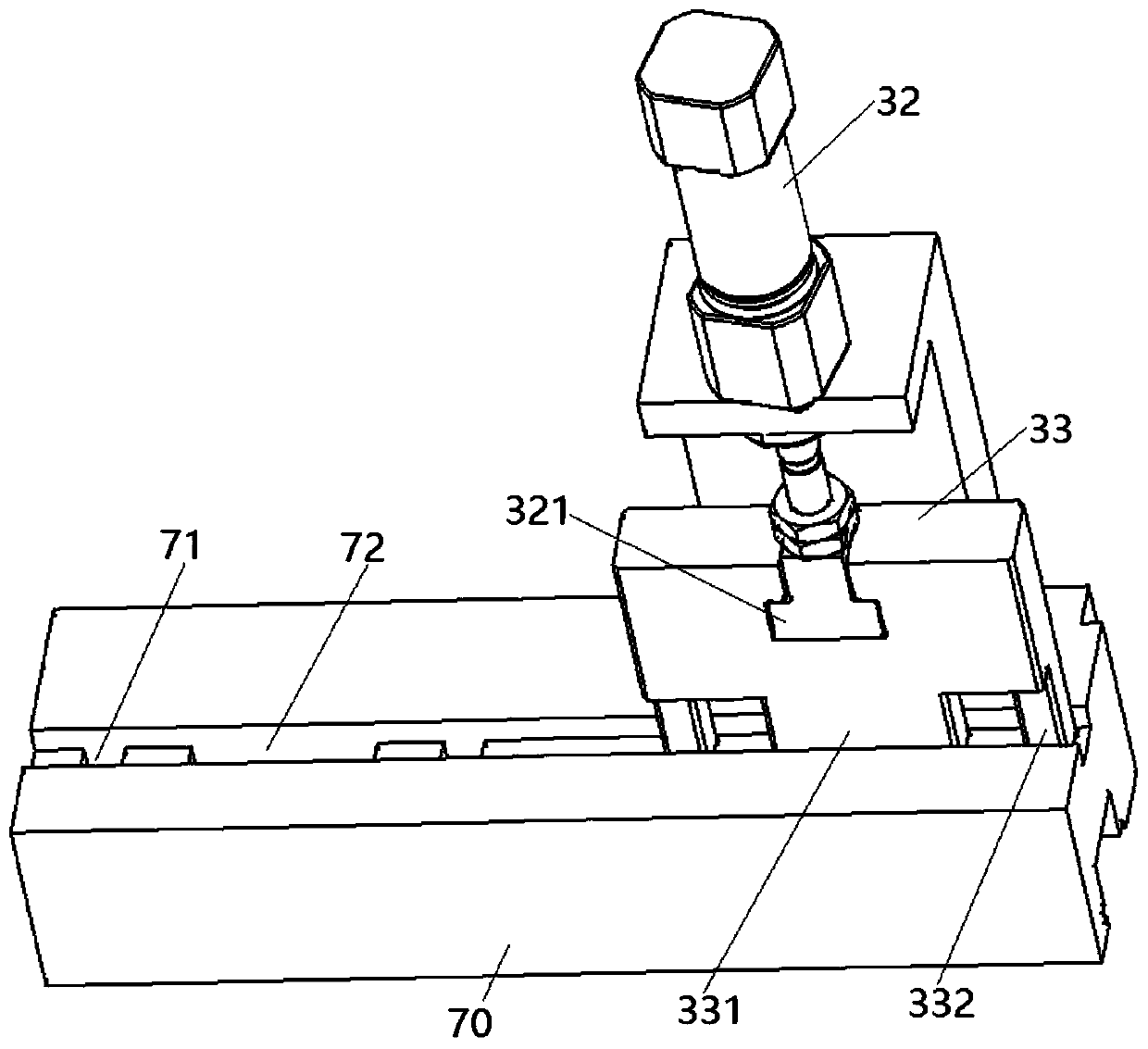
[0022] see figure 1 and figure 2 , an automatic embossing device according to the present invention includes a workbench 10, and also includes a feeding mechanism, an embossing mechanism and a discharging mechanism. The feeding mechanism includes a machine base 21 fixed on the workbench 10, the top surface of the machine base 21 is provided with a feeding groove 211 along its length direction, and a conveyor belt is erected in the feeding groove 211. The conveyor belt is driven by a stepping motor on one side of the support 21.

[0023] The embossing mechanism includes an embossing base 31 and an embossing cylinder 32 , and the embossing base 31 is fixed on the workbench 10 on one side of the machine base 21 . The embossing cylinder 32 is fixe...


PUM


Abstract

The invention discloses an automatic embossing device. The device comprises a feeding mechanism, an embossing mechanism and a discharging mechanism, wherein the feeding mechanism comprises a machine base fixed on a workbench, and a conveying belt is arranged in a feeding groove formed in the top surface of the machine base in an erecting mode; the embossing mechanism comprises an embossing base and an embossing air cylinder, a movable end of the embossing air cylinder is detachably connected with an embossing block, and the bottom of the embossing block is detachably provided with a concave-convex line plate; the discharging mechanism comprises a discharging air cylinder, a first discharging groove, a second discharging groove, a collecting hopper and an induction probe, the movable end ofthe discharging air cylinder is fixedly connected with the first discharging groove and can drive the first discharging groove to horizontally move in a front-and-back direction, the second discharging groove is formed in the right side of the first discharging groove, and the higher end of the second discharging groove is fixedly connected with the side part of the higher end of the first discharging groove; and the induction probe is arranged at a discharging end of the feeding groove. The device is compact in structure, convenient to use and capable of effectively conveying materials, andcan well cooperate with a machining device for operation, so that the precision of assembly line machining is greatly improved.

Description

technical field [0001] The invention relates to the field of mechanical equipment, in particular to an automatic embossing device. Background technique [0002] In the process of mechanical production and processing, it is often necessary to emboss the accessories. The traditional method is to place the accessories on the flattening workbench for flattening, and then transfer them to the embossing workbench for embossing. The operation is cumbersome. Time-consuming. There are also devices on the market that transport accessories to the embossing motor or flattening motor through conveyor belts for processing. However, most of these devices have complex structures, large volumes and high costs, and it is difficult to accurately control the distance of accessories transportation. At the same time, when carrying out processing operations on the conveyor belt, it is easy to cause the conveyor belt to be sunken due to the processing force, which not only easily damages the conve...

Claims


Application Information

Patent Timeline
Patent Type & Authority Patents(China)
IPC IPC(8): B21D43/12B21D43/10B21D43/00B21C51/00B21D45/04B21D13/02B21D21/00
CPCB21C51/00B21D13/02B21D21/00B21D43/003B21D43/10B21D43/12B21D45/04
Inventor 沈凡
Owner 嘉善翱鹰五金制品厂
Learn More