Cutting device for heat exchange pipe of chemical heat exchanger
A cutting device and heat exchanger technology, applied in positioning devices, manufacturing tools, metal processing and other directions, can solve the problems of difficult maintenance and repair, complex structural composition, troublesome operation, etc., and achieve low maintenance and repair costs, easy production and operation. handy effect
- Summary
- Abstract
- Description
- Claims
- Application Information
AI Technical Summary
Problems solved by technology
Method used
Image

Examples
Embodiment 1
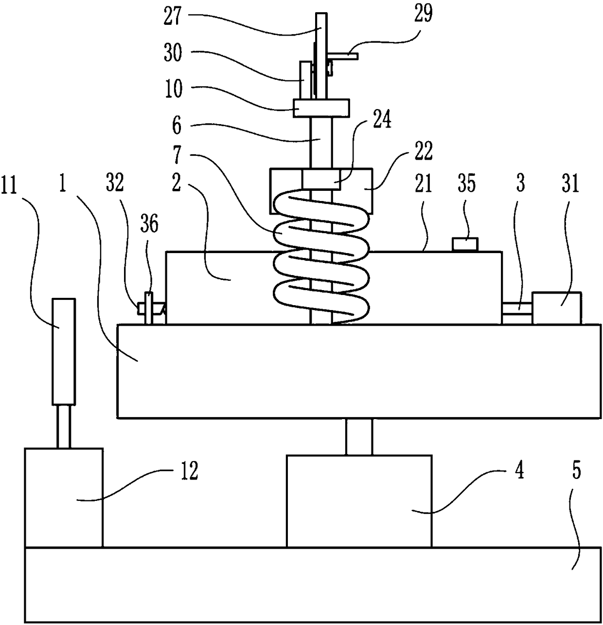
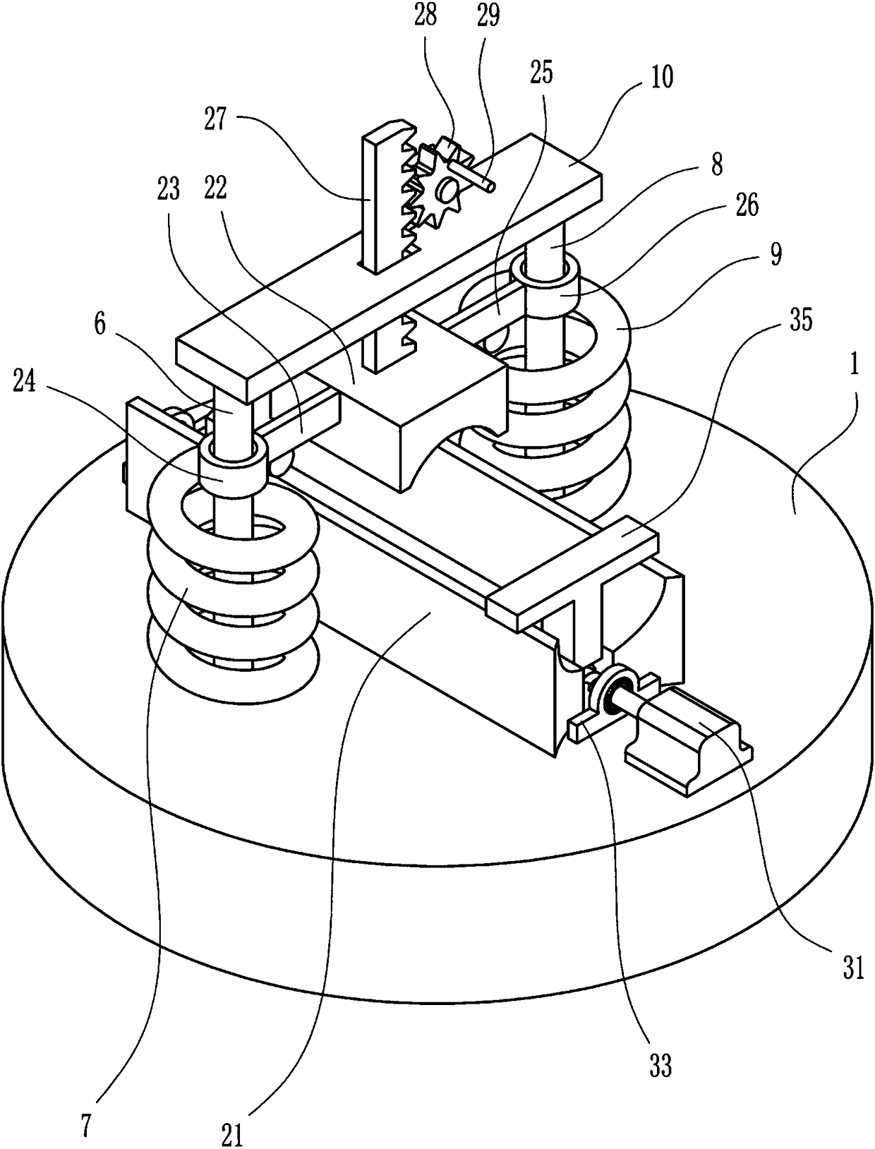
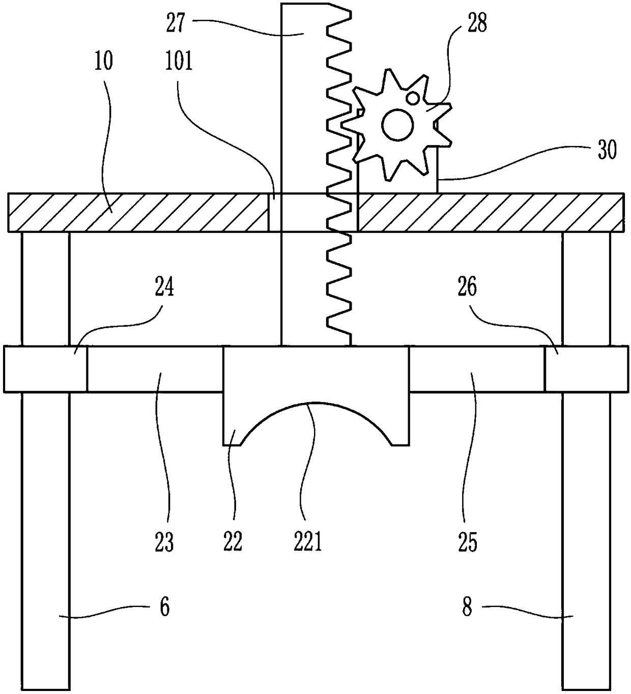
[0028] A cutting device for heat exchange tubes of chemical heat exchangers, such as Figure 1-6 As shown, it includes a workbench 1, a clamping device 2, a pushing device 3, a first rotating motor 4, a base 5, a first guide rod 6, a first spring 7, a second guide rod 8, a second spring 9, Top plate 10, cutting machine 11 and first cylinder 12; clamping device 2 and pushing device 3 are arranged on workbench 1; the upper end of the output shaft of first rotating motor 4 is connected to the middle part of the bottom of workbench 1 by welding Connection, the bottom of the first rotating motor 4 is connected with the top of the base 5 by means of bolt connection, and a first guide rod 6 and a second guide rod 8 are arranged symmetrically on both sides of the pushing device 3, and the first guide rod 6 and the second guide rod 8 are located above the workbench 1, the first guide rod 6 and the second guide rod 8 are connected to the workbench 1 by welding, the first spring 7 and th...
Embodiment 2
[0030] A cutting device for heat exchange tubes of chemical heat exchangers, such as Figure 1-6 As shown, it includes a workbench 1, a clamping device 2, a pushing device 3, a first rotating motor 4, a base 5, a first guide rod 6, a first spring 7, a second guide rod 8, a second spring 9, Top plate 10, cutting machine 11 and first cylinder 12; clamping device 2 and pushing device 3 are arranged on workbench 1; the upper end of the output shaft of first rotating motor 4 is connected to the middle part of the bottom of workbench 1 by welding Connection, the bottom of the first rotating motor 4 is connected with the top of the base 5 by means of bolt connection, and a first guide rod 6 and a second guide rod 8 are arranged symmetrically on both sides of the pushing device 3, and the first guide rod 6 and the second guide rod 8 are located above the workbench 1, the first guide rod 6 and the second guide rod 8 are connected to the workbench 1 by welding, the first spring 7 and th...
Embodiment 3
[0033] A cutting device for heat exchange tubes of chemical heat exchangers, such as Figure 1-6 As shown, it includes a workbench 1, a clamping device 2, a pushing device 3, a first rotating motor 4, a base 5, a first guide rod 6, a first spring 7, a second guide rod 8, a second spring 9, Top plate 10, cutting machine 11 and first cylinder 12; clamping device 2 and pushing device 3 are arranged on workbench 1; the upper end of the output shaft of first rotating motor 4 is connected to the middle part of the bottom of workbench 1 by welding Connection, the bottom of the first rotating motor 4 is connected with the top of the base 5 by means of bolt connection, and a first guide rod 6 and a second guide rod 8 are arranged symmetrically on both sides of the pushing device 3, and the first guide rod 6 and the second guide rod 8 are located above the workbench 1, the first guide rod 6 and the second guide rod 8 are connected to the workbench 1 by welding, the first spring 7 and th...
PUM
 Abstract
Description
Claims
Application Information
 - R&D
- Intellectual Property
- Life Sciences
- Materials
- Tech Scout
- Unparalleled Data Quality
- Higher Quality Content
- 60% Fewer Hallucinations
Browse by: Latest US Patents, China's latest patents, Technical Efficacy Thesaurus, Application Domain, Technology Topic, Popular Technical Reports.
© 2025 PatSnap. All rights reserved.Legal|Privacy policy|Modern Slavery Act Transparency Statement|Sitemap|About US| Contact US: help@patsnap.com