
Automatic device achieving partial drawing of metal piece

An automated device and metal parts technology, applied in metal processing equipment, grinding workpiece supports, grinders, etc., can solve the problem of not being able to meet the needs of product wire drawing well, unable to achieve partial wire drawing processing of products, and unstable manual wire drawing methods, etc. problems, to achieve the effect of improving market application value, simple structure and good processing stability

Pending Publication Date: 2018-06-15
SHANGHAI WUTENG METAL PROD CO LTD
View PDF0 Cites 2 Cited by
  • Summary
  • Abstract
  • Description
  • Claims
  • Application Information

AI Technical Summary

Problems solved by technology

Manual wire drawing refers to holding the product in your hand and aligning it with the abrasive belt for wire drawing. However, manual wire drawing is not only time-consuming and labor-intensive, but also has low work efficiency, and the manual wire drawing method is not stable. It is easy to produce defective products, and there are defects with a high defective rate
Mechanical wire drawing refers to the use of mechanical wire drawing devices to draw wires on products. Common mechanical wire drawing methods include: flat-press abrasive belt wire drawing, non-woven roller brush wire drawing, wide abrasive belt wire drawing, centerless grinding wire drawing, polishing machine wire drawing, etc. Although compared with Manual wire drawing has high work efficiency, but the current mechanical wire drawing device can only realize the overall wire drawing of the product surface, and cannot achieve partial wire drawing of the product, and cannot well meet the wire drawing requirements of the product

Method used


Image

  • Automatic device achieving partial drawing of metal piece
  • Automatic device achieving partial drawing of metal piece
  • Automatic device achieving partial drawing of metal piece

Examples


Embodiment

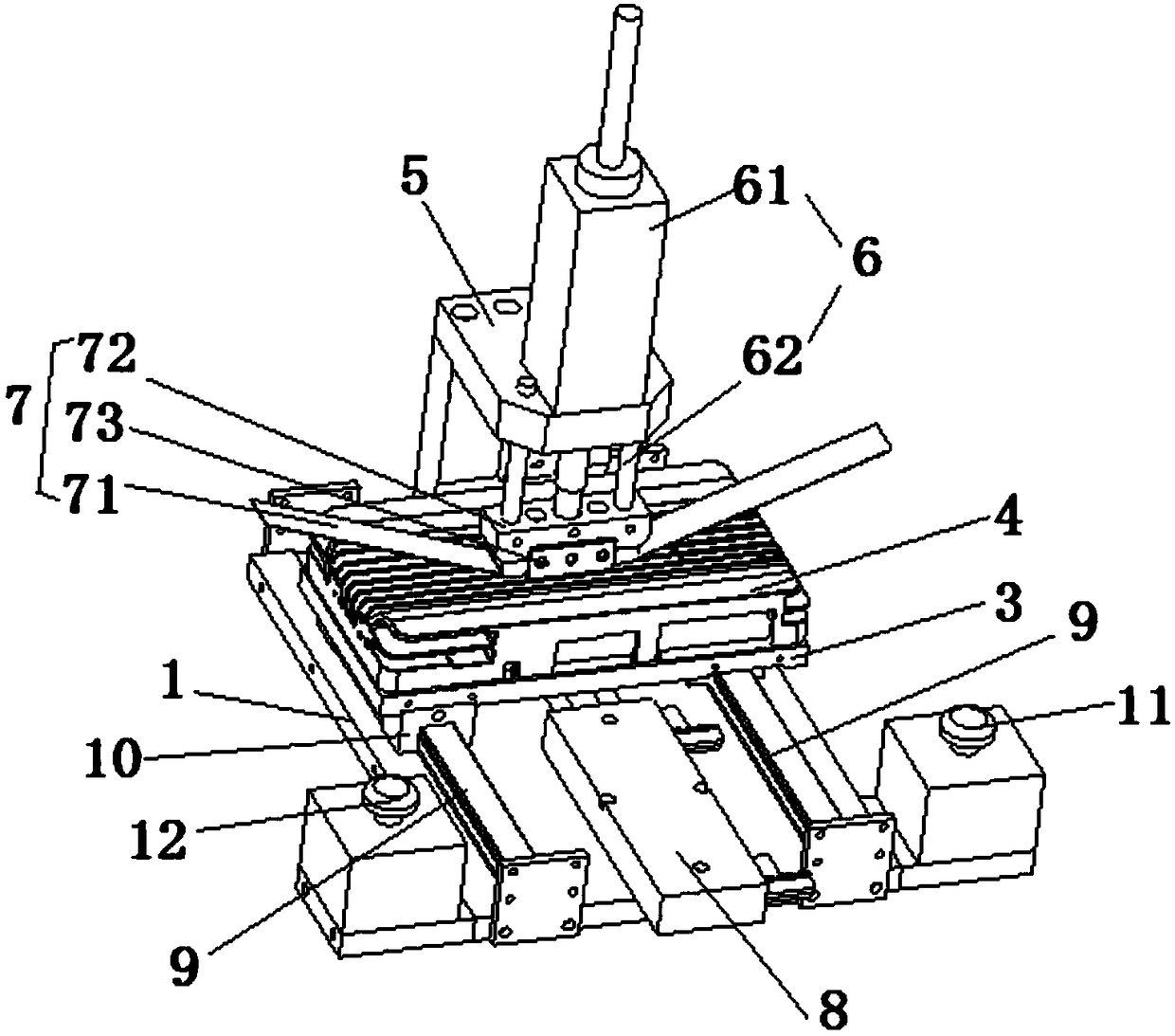
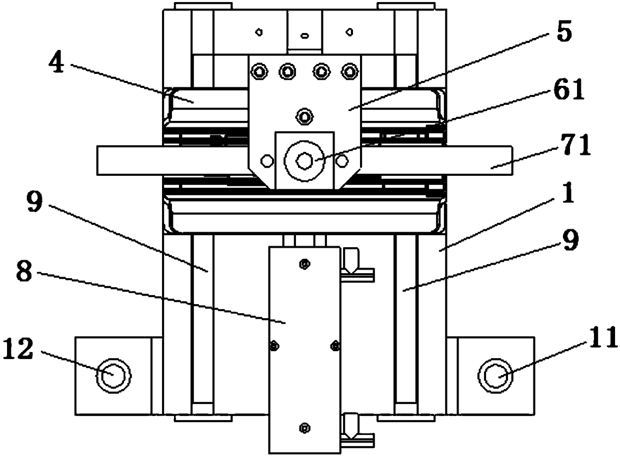
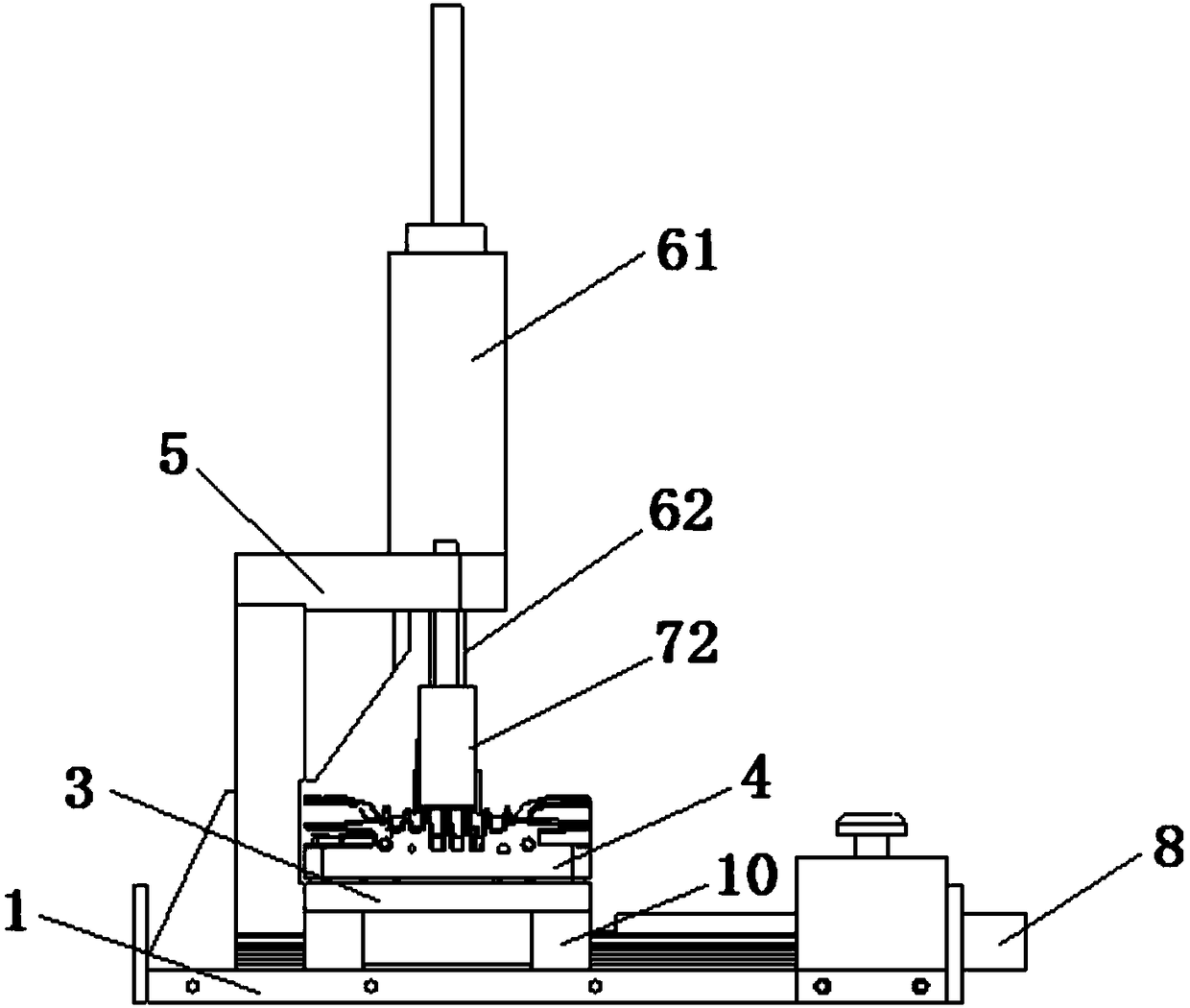
[0027] Please combine Figure 1 to Figure 5 As shown: an automatic device for realizing partial wire drawing of metal parts provided by the present invention, including a base 1 and a control device 2, the base 1 is provided with a horizontally movable positioning table 3, and the positioning table 3 is provided with There is a positioning mechanism compatible with the metal piece 4 to be drawn, a support 5 is vertically provided on the base 1, and a lifting mechanism 6 is provided on the top of the support 5, and the lifting mechanism 6 is connected to a wire drawing mechanism 7, The wire drawing mechanism 7 can move up and down linearly under the action of the lifting mechanism 6. The wire drawing mechanism 7 includes an abrasive belt 71 that can rotate in a vertical plane. The wire drawing parts 41 are parallel, the upper end surface of the abrasive belt 71 is provided with a wire drawing pressing block 72, the drawing pressing block 72 is connected with the lifting mechani...


PUM


Abstract

The invention discloses an automatic device achieving partial drawing of a metal piece. The automatic device achieving partial drawing of the metal piece comprises a base and a control device. The base is provided with a positioning platform face which can horizontally move. The positioning platform face is provided with a positioning mechanism which is matched with the metal piece to be subjectedto drawing. The base is vertically provided with a support. The top end of the support is provided with a lifting mechanism, and the lifting mechanism is connected with a drawing mechanism. The drawing mechanism comprises an abrasive belt which can rotate in a vertical plane. The polishing face of the abrasive belt is parallel to the drawn part of the metal piece to be subjected to drawing. The upper end face of the abrasive belt is provided with a drawing press block. The drawing press block is connected with a lifting mechanism, and the side face of the drawing press block is provided withan abrasive belt check block. The control device is electrically connected with the positioning platform face and the lifting mechanism. By means of the automatic device achieving partial drawing of the metal piece, partial drawing of a product can be automatically achieved, the working efficiency is high, the machining stability is good, the precision is high, the product percent of pass is high,and the application and popularization value is achieved.

Description

technical field [0001] The invention relates to an automatic device for realizing local wire drawing of metal parts, belonging to the technical field of mechanical processing. Background technique [0002] During the production and processing of metal parts, it is inevitable to undergo various surface treatments. The conventional surface treatments include sandblasting, polishing, embossing, electroplating, spraying and wire drawing. Compared with other surface treatments, the brushed treatment can make the metal surface obtain a non-mirror-like metallic luster, which has a very strong decorative effect like silk satin, as if giving new vitality and life to ordinary metals, so the brushed treatment has more and more More market recognition and wide application. [0003] The current drawing processing methods include manual drawing and mechanical drawing. Manual wire drawing refers to holding the product in your hand and aligning it with the abrasive belt for wire drawing. ...

Claims


Application Information

Patent Timeline
Patent Type & Authority Applications(China)
IPC IPC(8): B24B21/00B24B21/18B24B41/06
CPCB24B21/006B24B21/18B24B41/06
Inventor 沈超林艳谢朝江
Owner SHANGHAI WUTENG METAL PROD CO LTD
Learn More