Self-locking mechanism capable of preventing slide retreating and self-locking and unlocking method of self-locking mechanism

A technology of limiting mechanism and self-locking, applied in the field of self-locking mechanism to prevent travel position retreat, can solve the problems of reduced product quality, travel position backward, poor product dimensional accuracy, etc., and achieve the effect of maintaining production progress

Pending Publication Date: 2018-06-15
欧唐科技(深圳)有限公司
View PDF0 Cites 1 Cited by
  • Summary
  • Abstract
  • Description
  • Claims
  • Application Information

AI Technical Summary

Problems solved by technology

[0002] In the existing mold, when the driving mechanism directly pulls the core to move the position, the parts that match the position cannot be locked by the mold clamping force, and it is necessary to apply an external force to the matching parts through the driving mechanism. However, due to the inaccuracy of the driving mechanism, it is often As a result, the row position retreats under the action of injection molding pressure, resulting in defects such as excess glue, burrs, and flashes on the product, resulting in poor dimensional accuracy of the product, affecting the production progress, and reducing the quality of the product

Method used


Image

  • Self-locking mechanism capable of preventing slide retreating and self-locking and unlocking method of self-locking mechanism
  • Self-locking mechanism capable of preventing slide retreating and self-locking and unlocking method of self-locking mechanism
  • Self-locking mechanism capable of preventing slide retreating and self-locking and unlocking method of self-locking mechanism

Examples


Embodiment Construction

[0046] Embodiments of the present invention will be described in detail below.

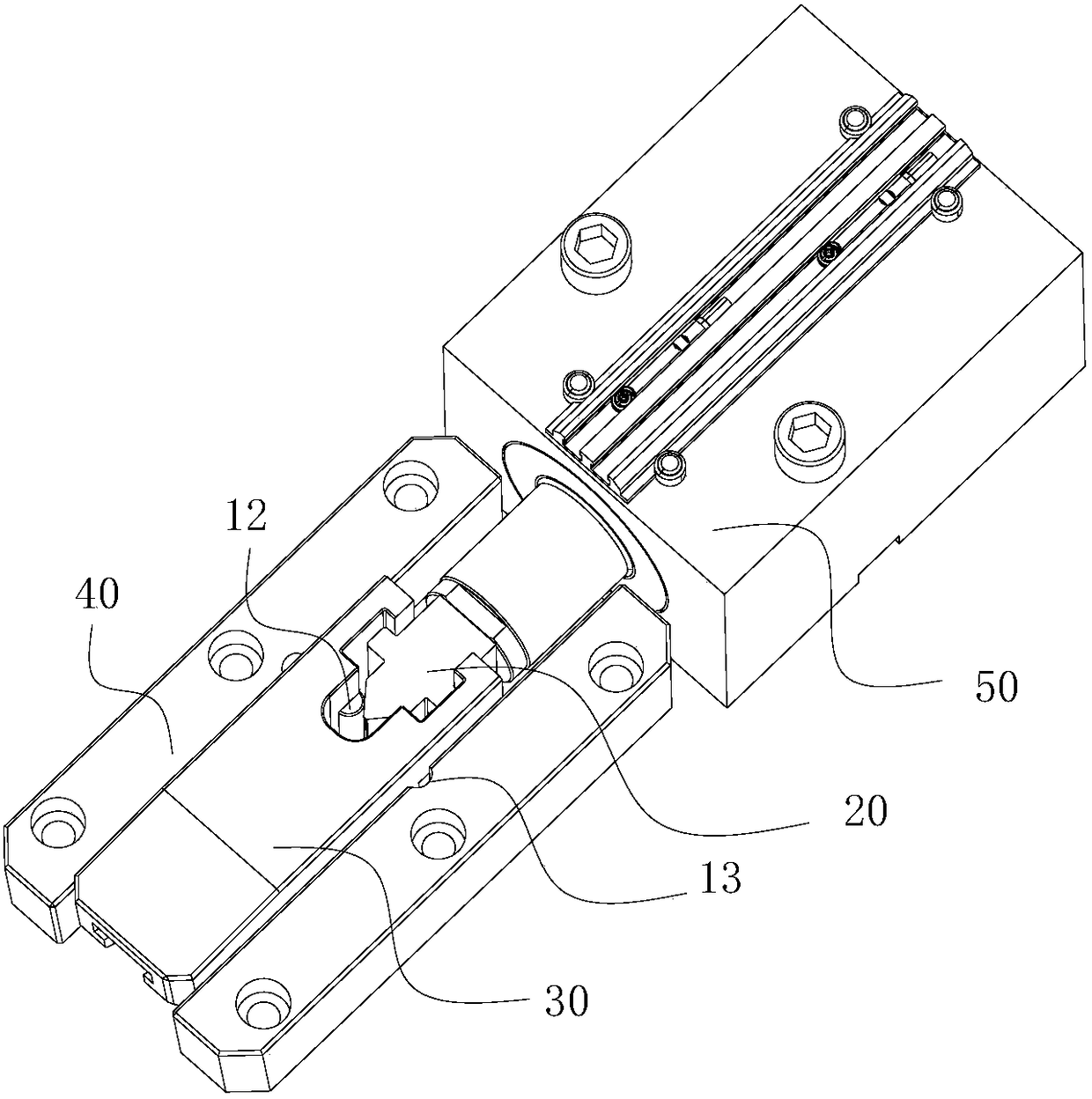
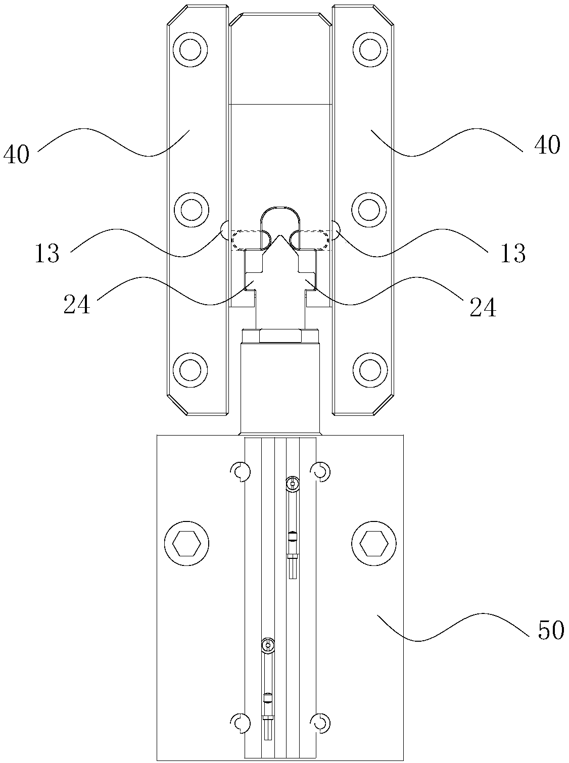
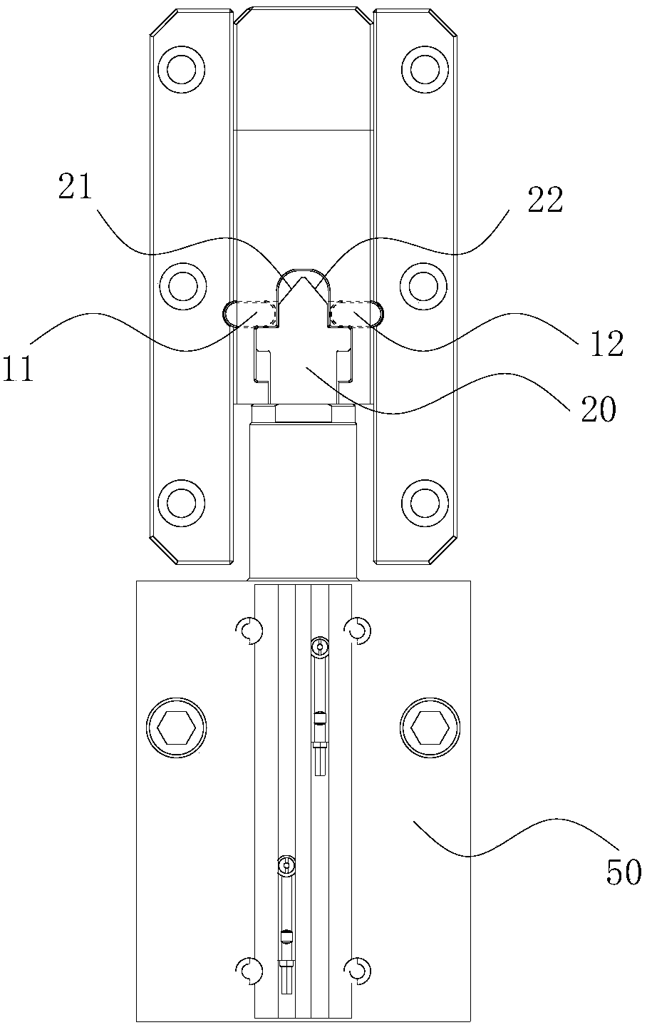
[0047] Such as Figure 1 to Figure 4 The shown self-locking mechanism for preventing row position backward includes row position push plate 30, fixed plate 40, limit mechanism 10, top block 20 and driving oil cylinder 50, and fixed plate 40 is placed on both sides of row position push plate 30, The end of the row position push plate 30 has a self-locking groove 31, the limit mechanism 10 is located inside the self-locking groove 31, the top block 20 is located at the notch of the self-locking groove 31, and the top of the top block 20 has an inclined top surface and a limit surface 23 , the limiting surface 23 is located below the inclined top surface, and the driving cylinder 50 is connected with the top block 20 to drive the movement of the top block 20;

[0048] The limiter mechanism 10 comprises a first limiter 11, a second limiter 12 and a limiter slot 13, the first limiter 11 and the second...


PUM


Abstract

The invention discloses a self-locking mechanism capable of preventing slide retreating and a self-locking and unlocking method of the self-locking mechanism. The self-locking mechanism capable of preventing slide retreating comprises a slide push plate, fixed plates, a limiting mechanism, an ejection block and a driving mechanism, the fixed plates are arranged on the two sides of the slide push plate, the tail end of the slide push plate is provided with a self-locking groove, the limiting mechanism is located inside the self-locking groove, the ejection block is located in a groove opening of the self-locking groove, the top of the ejection block is provided with an inclined top face and a limiting face, the limiting face is located below the inclined top face, the driving mechanism is connected with the ejection block and drives the ejection block to move, self-locking of the limiting mechanism can be achieved, the position of the slide push plate can be locked effectively, slide push plate retreating caused by too large injection molding pressure is prevented, the defects of too much glue, flashing, trimming and the like are prevented, and the quality of an injection molding product is guaranteed.

Description

technical field [0001] The invention relates to the technical field of injection molds, in particular to a self-locking mechanism for preventing a row from retreating and a self-locking and unlocking method thereof. Background technique [0002] In the existing mold, when the driving mechanism directly pulls the core to move the position, the parts that match the position cannot be locked by the mold clamping force, and it is necessary to apply an external force to the matching parts through the driving mechanism. However, due to the inaccuracy of the driving mechanism, it is often As a result, the line position retreats under the action of injection molding pressure, resulting in defects such as excess glue, burrs, and flashes on the product, resulting in poor dimensional accuracy of the product, affecting production progress, and reducing product quality. Contents of the invention [0003] The object of the present invention is to provide a self-locking mechanism for pre...

Claims


Application Information

Patent Timeline
IPC IPC(8): B29C45/26B29C45/33
CPCB29C45/2602B29C45/2606B29C45/33
Inventor 黄强何永强
Owner 欧唐科技(深圳)有限公司
Why Eureka
Try Eureka