Full-automatic vision printer

A printing machine, fully automatic technology, used in printing machines, rotary printing machines, screen printing machines and other directions, can solve problems such as cost increase, affecting PCB board calibration accuracy, affecting XYθ calibration work platform calibration accuracy, etc., to ensure quality. Effect

Inactive Publication Date: 2018-06-15
SHENZHEN HUANCHENG AUTOMATION EQUIP
View PDF0 Cites 5 Cited by
  • Summary
  • Abstract
  • Description
  • Claims
  • Application Information

AI Technical Summary

Problems solved by technology

[0003] There are some deficiencies in the traditional fully automatic visual printing machine: First, the separation of the PCB board and the stencil is realized by moving up and down the XYθ correction work platform, and the XYθ correction work platform is composed of an overlapping structure of multi-layer platforms, and then increases An up and down movement in the Z direction will inevitably affect the calibration accuracy of the platform, thereby affecting the calibration accuracy of the PCB board; the second is that the front and rear rails of the traditional transportation track cannot move relative to each other, and the distance is fixed, while the XYθ calibration work platform is up and down. When moving, it needs to pass between the two sub-tracks, so if the gap between the two sub-tracks is too small, the XYθ correction work platform cannot move up and down, and if the gap between the two sub-tracks is too large Large, some PCB boards cannot be transported, so the traditional automatic visual printing machine can only process PCB boards of the same width. If you want to process PCB boards with different widths, you have to buy different equipment, which greatly increases the cost; It is because the PCB board is fixed on the XYθ calibration work platform and moves up and down together with it, so a jig must be set on the XYθ calibration work platform to clamp and fix the PCB board. If the jig needs to be repaired and replaced, It is necessary to move to the XYθ calibration work platform, so it may affect the calibration accuracy of the XYθ calibration work platform, thereby affecting the calibration accuracy of the PCB board

Method used


Image

  • Full-automatic vision printer
  • Full-automatic vision printer
  • Full-automatic vision printer

Examples


Embodiment Construction

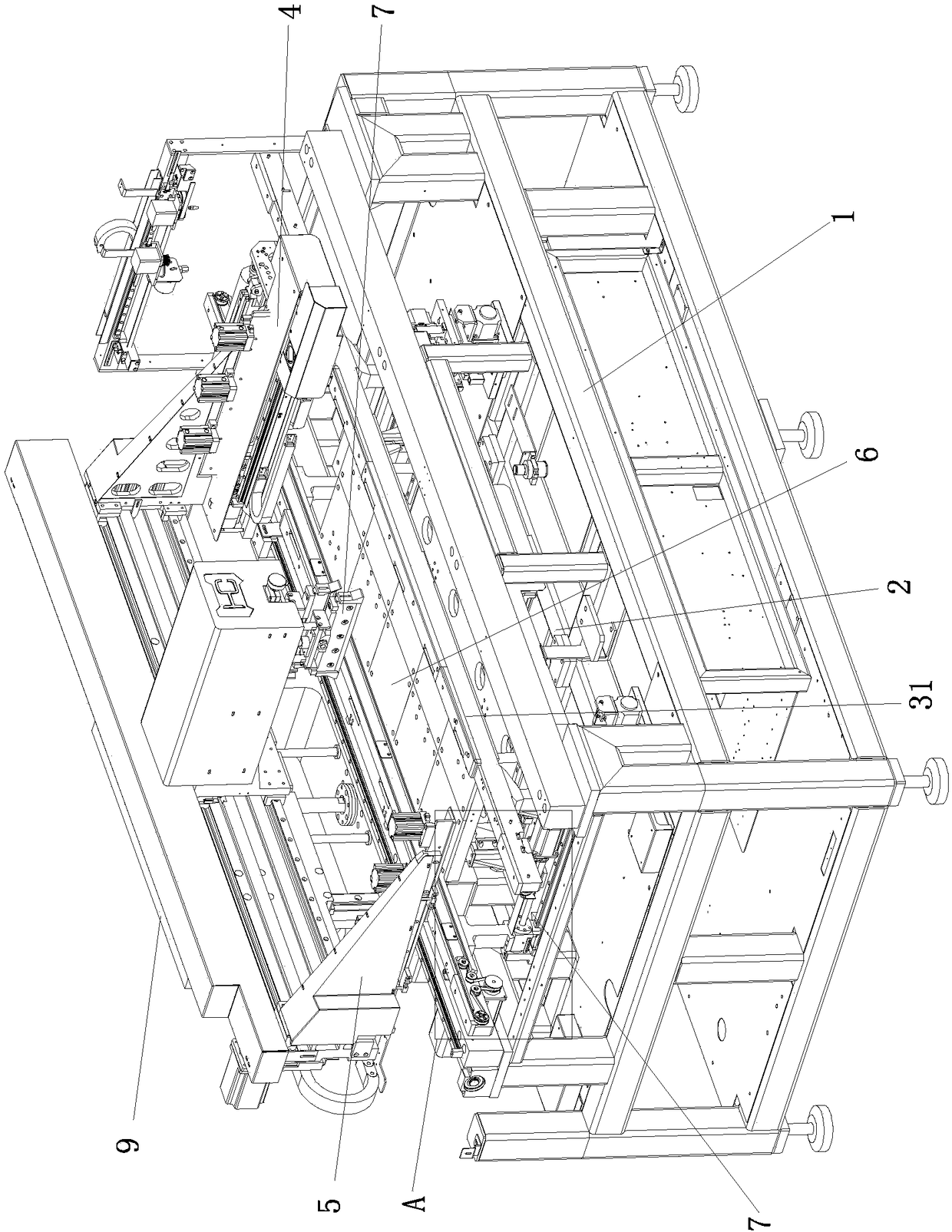
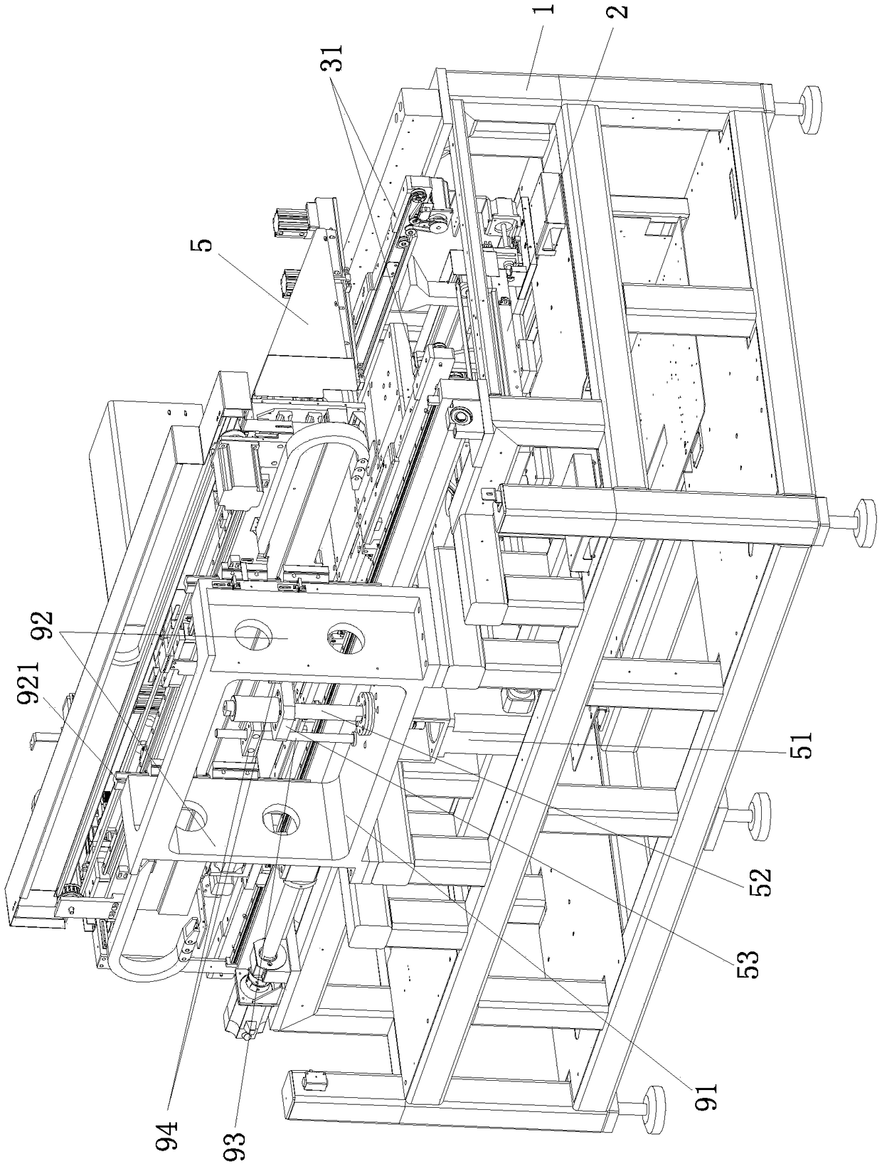
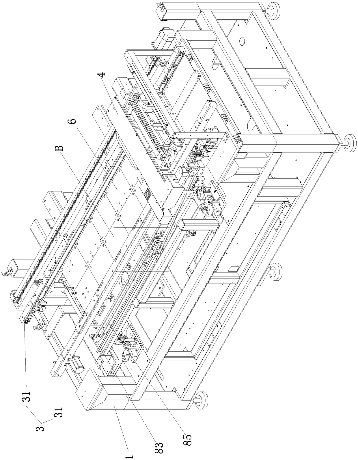
[0026] Such as Figures 1 to 6 As shown, the automatic visual printing machine of the present invention is used for solder paste printing of PCB boards. The automatic visual printing machine includes a frame 1, an XYθ correction work platform 2 connected to the frame 1, a transport track 3, CCD imaging system 4, steel mesh bracket 5, steel mesh 6 connected to said steel mesh bracket 5, scraper 61 connected to said steel mesh bracket 5 that can move up and down relative to left and right, said transport track 3 includes The front and rear two sub-tracks 31 that can be relatively close or far away, each sub-track 31 includes a support 32, a transport belt 33 arranged on the inside of the support 32, a first driving device for driving the transport belt 33, a fixed The splint 34 connected to the bracket 32 ​​and arranged on the outside of the conveyor belt 33, the splint 34 on the outside of the front and rear two-point track 31 are respectively used to clamp the front and rear e...


PUM


Abstract

The invention discloses a full-automatic vision printer. The full-automatic vision printer comprises a rack, an XYtheta correction work platform connected to the rack, a transportation track, a CCD image system, a steel net bracket, a steel net, a scraper and a lifting platform which is connected to the upper side of the XYtheta correction work platform in a relative up-down movement manner. The transportation track comprises a front branch track and a rear branch track which can relatively get close to each other or get away from each other. Each branch track comprises a support, a conveyingbelt arranged on the inner side of the support, and a clamping plate which is fixedly connected to the support and arranged on the outer side above the conveying belt. The steel net bracket is connected to the rack in a relative up-down movement manner. The distance between the two branch tracks can be adjusted according to the width of a PCB. The lifting platform can ascend to jack the PCB till the upper end face of the PCB is flush with the upper end face of the clamping plates, and then the two clamping plates clamp the front end and the rear end of the PCB correspondingly. The steel net bracket moves downwards, the steel net completely coincides with the PCB, then, the scraper conducts the solder paste printing action, and after solder paste printing is finished, the steel net bracketdrives the steel net to move upwards.

Description

technical field [0001] The invention relates to processing equipment for electronic products, in particular to a fully automatic visual printing machine for printing solder paste on PCB boards. Background technique [0002] A traditional fully automatic visual printing machine includes a frame, an XYθ correction work platform arranged on the frame, a transport track, a CCD imaging system, a steel mesh bracket arranged above the XYθ correction work platform, and a steel mesh bracket connected to the steel support The stencil and scraper at the lower end of the bracket, the XYθ correction work platform also moves up and down through a Z-axis drive device, the stencil bracket is relatively fixedly connected to the frame so that it cannot move up and down, and the CCD imaging system can perform X and Moving in the Y direction, the PCB is transported by the transport rail to the top of the XYθ correction work platform and then fixed. The CCD imaging system moves in and out from b...

Claims


Application Information

Patent Timeline
IPC IPC(8): B41F15/36B41F15/42B41F15/14H05K3/34
CPCB41F15/36B41F15/14B41F15/42B41P2215/50H05K3/34
Inventor 晏福平魏清罗记能陆志远
Owner SHENZHEN HUANCHENG AUTOMATION EQUIP
Why Eureka
Try Eureka