
A concentrated drainage structure of underground rainwater for townhouses

A technology for rainwater and villas, which is applied in the direction of drainage structures, sewage discharge, general water supply saving, etc. It can solve the problems of occupying the usable area of ​​residents, poor practicability, troublesome use, etc., and achieve the effect of saving resources and protecting the environment

Active Publication Date: 2020-09-25
珠海市建安集团有限公司
View PDF8 Cites 0 Cited by
  • Summary
  • Abstract
  • Description
  • Claims
  • Application Information

AI Technical Summary

Problems solved by technology

[0003] Today's various buildings make full use of the underground space to reduce the building. Under the floors, the building is designed with an underground garage to place vehicles to reduce the space occupied by the ground. However, with the rise of underground space, new problems have emerged in the construction and use of underground space. The problem of space waterproofing. The waterproof and drainage of the underground space is very important to the use of the entire building, and even affects the service life of the underground space. The underground space of existing townhouses is generally installed at the bottom of each villa. Drainage, this kind of drainage measures not only occupies the usable area of ​​the residents, but also is more troublesome to use, and at the same time, it cannot effectively drain and waterproof the underground space, so the practicability is poor

Method used


Image

  • A concentrated drainage structure of underground rainwater for townhouses
  • A concentrated drainage structure of underground rainwater for townhouses
  • A concentrated drainage structure of underground rainwater for townhouses

Examples


Embodiment Construction

[0019] The following will clearly and completely describe the technical solutions in the embodiments of the present invention with reference to the accompanying drawings in the embodiments of the present invention. Obviously, the described embodiments are only some, not all, embodiments of the present invention. Based on the embodiments of the present invention, all other embodiments obtained by persons of ordinary skill in the art without making creative efforts belong to the protection scope of the present invention.

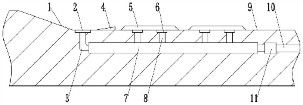
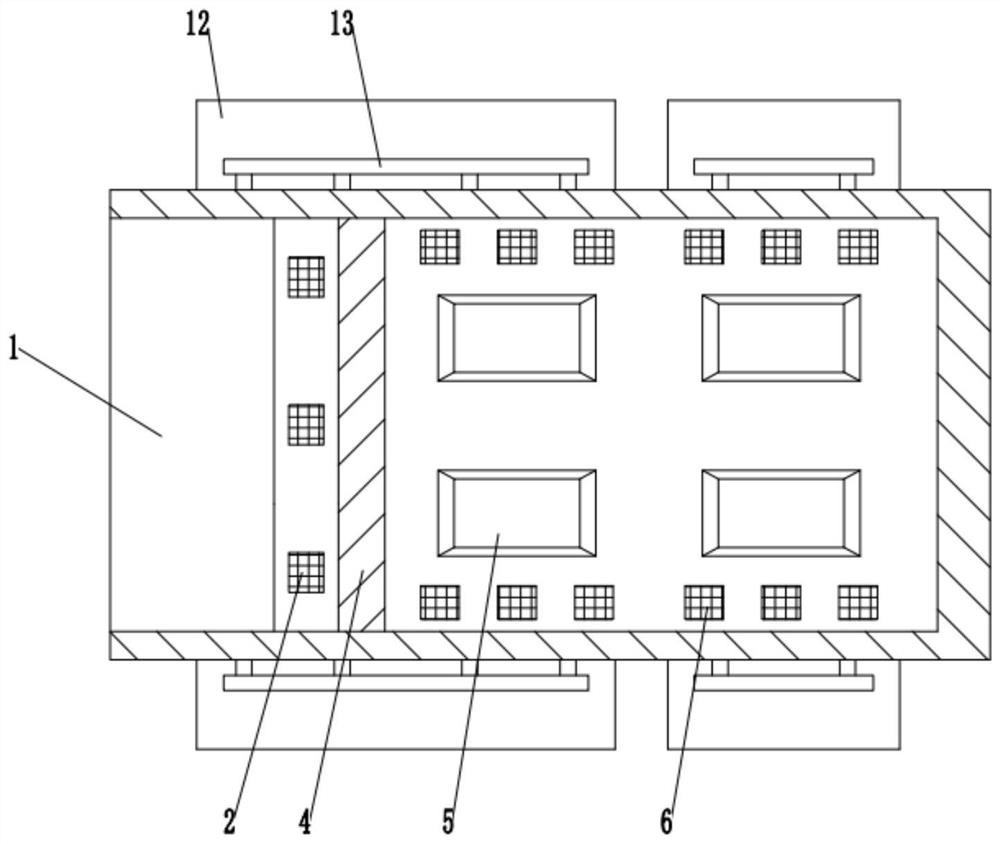
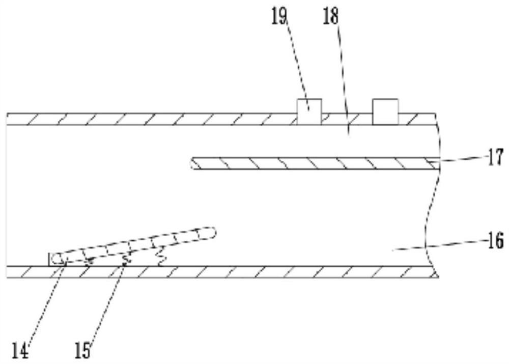
[0020] see Figure 1~3 , in an embodiment of the present invention, a townhouse underground rainwater centralized discharge structure, including an underground parking lot 9 and a blind ditch 7; the entrance of the underground parking lot 9 is obliquely and fixedly installed with an entrance and exit ramp 1, so that vehicles can enter and exit , the connection between the entrance and exit ramp 1 and the underground parking lot 9 is provided with a rainwater b...


PUM


Abstract

The invention discloses an underground rainwater centralized discharge structure for a townhouse. The underground rainwater centralized discharge structure comprises an underground parking garage anda blind rain, wherein an access ramp is fixedly arranged on an entrance of the underground parking garage in an inclined mode; a rain buffer zone is arranged on the part where the access ramp and theunderground parking garage are connected; a slope is fixedly arranged on the rain buffer zone; a plurality of gutter inlets are additionally arranged on the part, at the left side of the slope, of therain buffer zone; a plurality of parking seats are fixedly arranged in the underground parking garage; and a plurality of second gutter inlets are additionally uniformly arranged in the underground parking garage. According to the underground rainwater centralized discharge structure provided by the invention, by fixedly arranging the slope on the part where the underground parking garage and theaccess ramp are connected, rainwater is prevented from directly flowing into the parking garage in rainy days; in addition, by arranging the plurality of first gutter inlets in the front side of theslope, the discharge of the rainwater into the blind drain is accelerated; and meanwhile, by fixedly arranging the parking seats, which are represented as trapezoidal platforms, in the underground parking garage, cars are prevented from getting into direct contact with the rainwater.

Description

technical field [0001] The invention relates to the technical field of rainwater drainage, in particular to an underground rainwater centralized drainage structure for townhouses. Background technique [0002] Townhouses originated in the 1940s and 1950s during the New Town period in England, and they are common in Europe and the United States. Townhouses are generally composed of several or more than a dozen low-rise residential buildings less than 5 floors connected in parallel. Each building has an area of ​​about 150-200 square meters. square meters, and there is also a dedicated parking space or garage. In the West, townhouses are owned by the middle class or upstarts, while in China they belong to the high-spending crowd. [0003] Today's various buildings make full use of the underground space to reduce the building. Under the floors, the building is designed with an underground garage to place vehicles to reduce the space occupied by the ground. However, with the r...

Claims


Application Information

Patent Timeline
Patent Type & Authority Patents(China)
IPC IPC(8): E03F1/00E03F5/00E03F5/04E03B3/02
CPCE03B3/02E03F1/002E03F5/00E03F5/0401Y02A20/108Y02A30/60
Inventor 闵明熊朝军刘军亮何文财
Owner 珠海市建安集团有限公司
Learn More