Equipment and method for controlling accuracy of sticking of wall tile and caulked joint

A technology of wall bricks and equipment, which is applied in the direction of construction and building construction, and can solve problems such as uneven mortar joints, sinking of facing bricks, and long time consumption

Pending Publication Date: 2018-06-15
王广志
View PDF0 Cites 2 Cited by
  • Summary
  • Abstract
  • Description
  • Claims
  • Application Information

AI Technical Summary

Problems solved by technology

[0003] In the process of using traditional technology to install facing bricks, due to the fluidity of the mortar and the facing bricks are easily affected by temperature and humidity and the load of the material itself, the pasted facing bricks will sink and the mortar joints will be uneven so that the entire wall will be affected. flatness
Although the flatness of the lower pad can be adjusted repeatedly with the help of wood blocks, newspapers, bricks, etc., the effect is not ideal due to the nature of the material itself
The existing technology of veneering tiles generally uses wood blocks, newspapers, bricks, etc. to repeatedly adjust the leveling of the lower pads. There are two main disadvantages in doing so: one is that workers do not have suitable tools, and can only adjust manually through naked eyes. The time is long and the efficiency is low. The second is that the quality requirements of workers are high. It is difficult for ordinary workers to guarantee the quality of wall tile laying and the accuracy of mortar joints.

Method used


Image

  • Equipment and method for controlling accuracy of sticking of wall tile and caulked joint

Examples


Embodiment 1

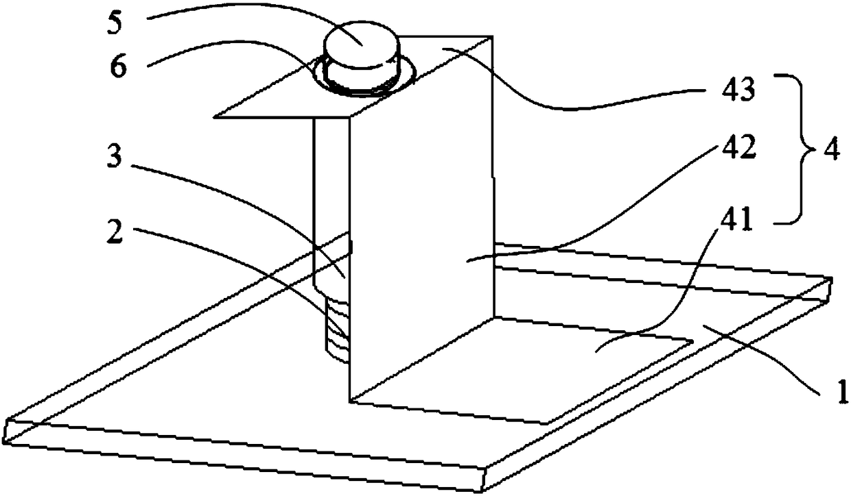
[0042] Such as figure 1 As shown, this embodiment provides a device for controlling the accuracy of wall tile inlay and caulking, including a chassis 1, an adjustment shaft 2, an adjustment tube 3, a strut sheet 4 and a fixing member 5; the lower end of the adjustment shaft 2 Vertically and fixedly connected to the chassis 1, the adjusting tube 3 is sleeved on the adjusting shaft 2 and screwed to it, the upper end of the adjusting tube 3 is fixedly connected with the fixing piece 5, and the upper end of the strut piece 4 is rotatably installed on the adjusting tube 3 and the fixing piece 5 Between them, a first horizontal piece 41 is formed at the lower end of the strut piece 4 for horizontally supporting the spacer.

[0043] Preferably, the upper end of the strut piece 4 is provided with a mounting hole, the fixing member 5 is a bolt, and the bolt passes through the mounting hole and is threadedly connected with the upper end of the adjusting tube 3 with internal threads, and...

Embodiment 2

[0050] This embodiment provides a method for controlling the accuracy of wall tile inlaying and caulking. This embodiment uses the equipment in Embodiment 1, which has all the technical features and beneficial effects in Embodiment 1, including the following steps:

[0051] S1, place the equipment at both ends of the front side of the wall that needs to be inlaid with wall tiles, according to the length of the wall, do not add or add some equipment between the two ends of the equipment, and place the spacer on the first horizontal sheet 41 of all equipment superior;

[0052] S2, use a spirit level to detect the levelness of the pad, and adjust the height of the first level sheet 41 by rotating the adjustment tube 3 of each device according to the detection result until the pad reaches the level;

[0053] S3, first inlay two rows of wall tiles on the left and right sides of the wall from bottom to top, then inlay a row of wall tiles below the wall along the spacer, and then inl...

Embodiment 3

[0068] Such as figure 1 As shown, this embodiment provides a device for controlling the accuracy of wall tile inlay and caulking, including a chassis 1, an adjustment shaft 2, an adjustment tube 3, a strut sheet 4 and a fixing member 5; the lower end of the adjustment shaft 2 Vertically and fixedly connected to the chassis 1, the adjusting tube 3 is sleeved on the adjusting shaft 2 and screwed to it, the upper end of the adjusting tube 3 is fixedly connected with the fixing piece 5, and the upper end of the strut piece 4 is rotatably installed on the adjusting tube 3 and the fixing piece 5 Between them, a first horizontal piece 41 is formed at the lower end of the strut piece 4 for horizontally supporting the spacer.

[0069] Preferably, the lower end of the adjustment shaft 2 is welded to the base, and the chassis 1 is placed on the ground by setting the chassis 1 to provide a stable support foundation for the equipment; the adjustment shaft 2 connected to the chassis 1 by ve...


PUM


Abstract

The invention relates to equipment and method for controlling the accuracy of sticking of a wall tile and a caulked joint. The equipment comprises a chassis, an adjusting shaft, an adjusting pipe, a supporting rod piece and a fixing piece. The lower end of the adjusting shaft is perpendicularly and fixedly connected to the chassis, the adjusting pipe is arranged on the adjusting shaft in a sleeving mode and is in threaded connection with the adjusting shaft, the upper end of the adjusting pipe is fixedly connected with the fixing piece, the upper end of the supporting rod piece is rotatably mounted between the adjusting pipe and the fixing piece, and a first horizontal piece used for horizontally supporting a cushion ruler is formed at the lower end of the supporting rod piece. The methodutilizes the equipment to adjust the levelness of the cushion ruler, one column on one of the two sides of a wall face is firstly paved with wall tiles from bottom to top by being tightly attached tothe cushion ruler, then another column on the other one of the two sides of the wall face is paved with the wall tiles, one column tightly attached to the cushion ruler is paved, the uppermost columnis paved then, and finally the rest wall face is stuck sequentially from left to right and from top to bottom. By utilizing the adjustability of the equipment which cooperates with the cushion ruler,the sticking position can be fixed in advance by using the method, the difficulty that the traditional sticking levelness and the flatness of a wall tile are difficult to control is overcome, and thepurpose that the flatness of sticking of the wall tile is controlled is achieved.

Description

technical field [0001] The invention relates to the field of building decoration, in particular to a device and a method for controlling the accuracy of wall tile inlaying and caulking. Background technique [0002] With the development of the construction industry, the decoration grade of buildings has also been improved. Due to its neat appearance, beautiful appearance and strong corrosion resistance, wall tiles have become a commonly used material and have been welcomed and concerned by the industry. According to "Construction Technology and Acceptance Standards for Inlay Engineering" stipulates that the current wall and wall tile inlay process can be roughly described as: base treatment - plastering the bottom ash - selection of bricks - infiltration - brick arrangement - spring line - sticking standard points - paving Wall tiles - joint cleaning. After plastering the bottom layer of dust, according to the designed building elevation, pop up the 50CM line on the wall to...

Claims


Application Information

Patent Timeline
Patent Type & Authority Applications(China)
IPC IPC(8): E04F21/18
CPCE04F21/1877
Inventor 王广志史丽男于炳安臧国才宋彦平胡新炜
Owner 王广志
Why Eureka
Try Eureka