State detection circuit and a state detection method of electromagnetic brake
A technology of electromagnetic brake and state detection
- Summary
- Abstract
- Description
- Claims
- Application Information
AI Technical Summary
Problems solved by technology
Method used
Image
Examples
no. 4 example
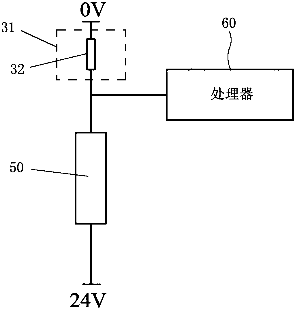
[0092] According to the fourth embodiment of the present invention, the state detection circuit may include an acquisition unit 31 , an amplification unit 52 , a comparison unit 55 , a reference signal generation unit 51 and a processor 60 .
[0093] The acquisition unit 31 may include a sampling resistor 32, which may be connected in series with the coil 50 of the electromagnetic brake, and the amplification unit 52 may amplify the acquisition signal of the acquisition unit 31 (for example, the voltage across the sampling resistor 32).
[0094] The amplification unit 52 may be an operational amplifier or other types of amplifiers. Specifically, the positive input terminal and the negative input terminal of the amplifying unit 52 may be respectively connected to both ends of the sampling resistor 32, and resistors R6 and R7 connected in parallel may be connected between the negative input terminal and the output terminal of the amplifying unit 52, And the amplification gain (i...
PUM
 Abstract
Description
Claims
Application Information
 - R&D
- Intellectual Property
- Life Sciences
- Materials
- Tech Scout
- Unparalleled Data Quality
- Higher Quality Content
- 60% Fewer Hallucinations
Browse by: Latest US Patents, China's latest patents, Technical Efficacy Thesaurus, Application Domain, Technology Topic, Popular Technical Reports.
© 2025 PatSnap. All rights reserved.Legal|Privacy policy|Modern Slavery Act Transparency Statement|Sitemap|About US| Contact US: help@patsnap.com


