Solar indoor air humidity control device

A technology for indoor air humidity and control devices, which is applied in air conditioning systems, climate sustainability, space heating and ventilation, etc., can solve the problems of limited humidification range, high risk to children, and increased household expenses, and achieves simple structure, The effect of reducing security risks and saving resources

Inactive Publication Date: 2018-06-15
胡铭轩
View PDF0 Cites 1 Cited by
  • Summary
  • Abstract
  • Description
  • Claims
  • Application Information

AI Technical Summary

Problems solved by technology

[0002] In northern families, the air in the home is relatively dry no matter in summer or winter. In the past, many families chose to put a basin of water in the bedroom and living room at home to increase the humidity of the air. With the improvement of people's living standards, Some families spend money to buy air humidification equipment, but they all need to consume electric energy. The humidification range of ordinary air humidification equipment is limited. There are still the following problems in the use of ordinary humidification equipment: because ordinary humidification equipment needs to be connected to the power supply, the voltage level exceeds the normal The maximum voltage that the human body can withstand is very dangerous for children; the humidification range of ordinary humidification equipment is limited, and due to the limitation of the humidification range of humidification equipment, family expenses are increased

Method used


Image

  • Solar indoor air humidity control device

Examples


Embodiment Construction

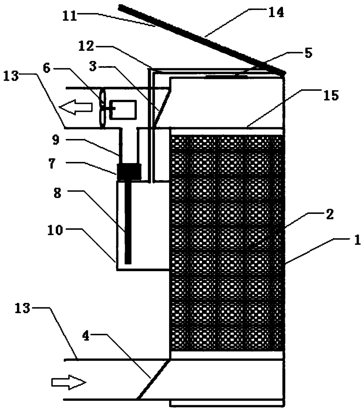
[0023] Such as figure 1 As shown, the present invention provides a solar indoor air humidity control device, including a dehumidification unit, a humidification unit, a solar power supply unit and a water condensation unit. , the upper ventilation valve 3 and the lower ventilation valve 4 that are located on the outer wall of the drying box 1, the one-way outlet valve 5 that is located at the top of the drying box 1, and the fan 6 that is located on the outside of the drying box 1 and is close to the upper ventilation valve 3; The unit is below the fan 6, including an ultrasonic atomizer 7, a water absorption rod 8 connected to the lower end of the ultrasonic atomizer 7, and a mist conduit 9 connected to the upper end of the ultrasonic atomizer 7, and the water absorption rod 8 is located in the water storage tank 10 The water condensation unit includes a condensation plate 11 and a water guide 12 located below the condensation plate 11, the front part of the water guide 12 is...


PUM


Abstract

The invention discloses a solar indoor air humidity control device comprising a dehumidification unit, a humidification unit, a solar power supply unit and a water condensation unit. The dehumidification unit comprises a drying box, a drying agent arranged in the drying box, an upper ventilation valve, a lower ventilation valve, a one-way exhaust valve arranged on the top of the drying box and a fan arranged on the outer portion of the drying box, and the upper ventilation valve and the lower ventilation valve are arranged on the outer wall of the drying box. The humidification unit is mainlycomposed of an ultrasonic atomizer. The water condensation unit comprises a condensation plate and a water guide pipe arranged below the condensation plate. The tail end of the water guide pipe is connected with a water storage tank. The condensation plate is arranged above the drying box. The whole device is arranged outdoors and communicates with indoor air through an air guide pipe. The dryingagent can be repeatedly used, moisture absorbed from air is atomized and then scattered in air, water cyclic utilization is achieved, resources are saved, and the production cost is lowered. Besides,a solar cell panel supplies power to the solar indoor air humidity control device, the solar indoor air humidity control device is environmentally friendly and safe.

Description

technical field [0001] The invention belongs to the technical field of humidity control, and in particular relates to a solar indoor air humidity control device. Background technique [0002] In northern families, the air in the home is relatively dry no matter in summer or winter. In the past, many families chose to put a basin of water in the bedroom and living room at home to increase the humidity of the air. With the improvement of people's living standards, Some families spend money to buy air humidification equipment, but they all need to consume electric energy. The humidification range of ordinary air humidification equipment is limited. There are still the following problems in the use of ordinary humidification equipment: because ordinary humidification equipment needs to be connected to the power supply, the voltage level exceeds the normal The maximum voltage that the human body bears is more dangerous for children; the humidification range of ordinary humidifica...

Claims


Application Information

Patent Timeline
IPC IPC(8): F24F1/02F24F3/14F24F11/89
CPCF24F3/14F24F3/1423Y02B30/70
Inventor 胡铭轩
Owner 胡铭轩
Why Eureka
Try Eureka