Supercharge Your Innovation With Domain-Expert AI Agents!

A Transform Domain Beamforming Method Based on Expanded Aperture Sonar

A transform domain and sonar technology, applied in the field of transform domain beamforming based on expanded aperture sonar, can solve the problem of reducing the range and clarity of sonar images

Active Publication Date: 2021-08-20
HARBIN ENG UNIV
View PDF20 Cites 0 Cited by
  • Summary
  • Abstract
  • Description
  • Claims
  • Application Information

AI Technical Summary

Problems solved by technology

However, in engineering applications, completely orthogonal signals do not exist, and the high cross-correlation between transmitted signals will cause the range side lobes to increase, reducing the range clarity of the sonar image

Method used


Image

  • A Transform Domain Beamforming Method Based on Expanded Aperture Sonar
  • A Transform Domain Beamforming Method Based on Expanded Aperture Sonar
  • A Transform Domain Beamforming Method Based on Expanded Aperture Sonar

Examples


specific Embodiment 1

[0035] In this example, the system parameters: the receiving array is a one-dimensional linear array, the angular beamwidth is 1.5°, the working frequency of the receiving array is 60kHz, the sound velocity is 1500m / s, the operating distance is 50m, and the signal sampling rate is 300kHz.

[0036] 1. Calculation process:

[0037] Assuming that the receiving array is a uniform linear array, and the distance between adjacent array elements is half the wavelength of the operating frequency of the receiving array, in order to meet the requirements of the angular beamwidth of the system, according to the formula,

[0038]

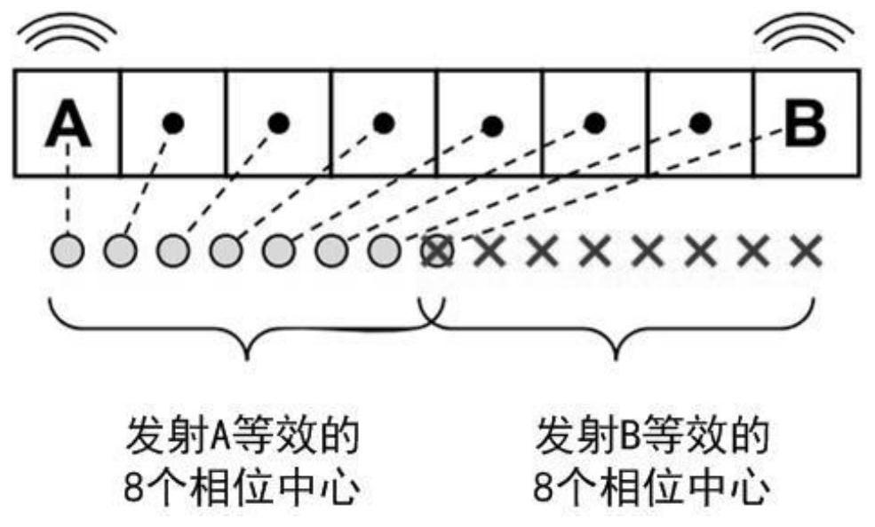
[0039] It can be calculated that the number of array elements in the actual receiving array is designed to be 36, and two transmitting arrays are arranged at both ends of the receiving array.

[0040] According to the calculated receive array parameters, given by Figure 4 The simulation shows that the beam width of the system after expanding the aperture is...

specific Embodiment 2

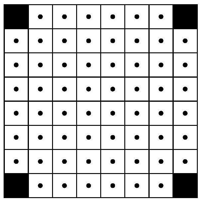
[0046] 1. First, according to the requirements of the sonar system index, according to the principle of the phase center of the equivalent array element of the expanded aperture sonar, that is, a transmitting array element and a receiving array element form a module, and the phase center of this module is located at the geometry of the two array elements. In the center, reasonably arrange the positions of the transmitting array and receiving array. If the sonar receiving array is a one-dimensional array, place the two transmitting arrays at both ends of the receiving array; Four emission arrays are arranged around the figure 1 with figure 2 shown. Assuming a uniform rectilinear receiving array, the distance between adjacent array elements is half a wavelength, the number of array elements is M, and two transmitting arrays are arranged at both ends of the array, then the angular beamwidth of the expanded aperture sonar is expressed as

[0047]

[0048] In the formula, BW...


PUM


Abstract

The invention discloses a transformation domain beamforming method based on an expanded aperture sonar, which belongs to the field of underwater acoustic signal processing. The invention includes: according to the requirements of the sonar system index, according to the principle of the phase center of the equivalent array element of the expanded aperture sonar, that is, a transmitting array element and a receiving array element form a module, and the phase center of this module is located at the center of the two array elements Geometric center, rationally arrange the position of the transmitting array and receiving array; according to the arranged transmitting and receiving array, at the end of the transmitting base array, the transmitting array simultaneously transmits mutually orthogonal waveforms; the receiving array receives the reflected signal of the target, that is, the echo signal; In the transform domain, the wave signal is subjected to receiving beamforming processing respectively, and the receiving beamforming is performed by transform domain filtering; for the signal after receiving beamforming processing in the transform domain, beamforming is used to compensate the time delay difference formed by different transmitting arrays, and then the expanded aperture acoustic signal is obtained. Nano's range to angle to the sonogram.

Description

technical field [0001] The invention belongs to the field of underwater acoustic signal processing, and in particular relates to a transformation domain beamforming method based on an expanded aperture sonar. Background technique [0002] In recent years, multi-beam image sonar technology has been widely used in the fields of seabed topographic mapping, oil pipeline detection and underwater target detection. In order to obtain high-definition sonar images, it is necessary to improve the range direction resolution and angular resolution. [0003] In a broadband signal system, the distance resolution is usually determined by the effective bandwidth of the received signal, while the angular resolution is usually determined by the effective aperture of the receiving array and the frequency of the received signal. In practical applications, changing the specific operating frequency range of image sonar in a specific application field will lead to a decrease in its detection perf...

Claims


Application Information

Patent Timeline
Patent Type & Authority Patents(China)
IPC IPC(8): G01S7/539
CPCG01S7/539
Inventor 朴胜春闫路郭微
Owner HARBIN ENG UNIV
Features
  • R&D
  • Intellectual Property
  • Life Sciences
  • Materials
  • Tech Scout
  • Unparalleled Data Quality
  • Higher Quality Content
  • 60% Fewer Hallucinations
Learn More