Antenna panel assembling structure

An assembly structure and antenna panel technology, which is applied to antennas, antenna supports/mounting devices, electrical components, etc., can solve problems such as limiting antenna accuracy, weakening antenna surface reflection efficiency, and reducing antenna reinstallation accuracy, so as to improve reflection efficiency , Simple structure, easy disassembly and assembly

Pending Publication Date: 2018-06-15
NO 54 INST OF CHINA ELECTRONICS SCI & TECH GRP
View PDF0 Cites 8 Cited by
  • Summary
  • Abstract
  • Description
  • Claims
  • Application Information

AI Technical Summary

Problems solved by technology

[0003] However, since each panel usually has more than 3 connection points, local stress will be generated during the assembly process of the panel, which will

Method used


Image

  • Antenna panel assembling structure
  • Antenna panel assembling structure

Examples


Example Embodiment

[0017] The present invention will be further described below in conjunction with the drawings.

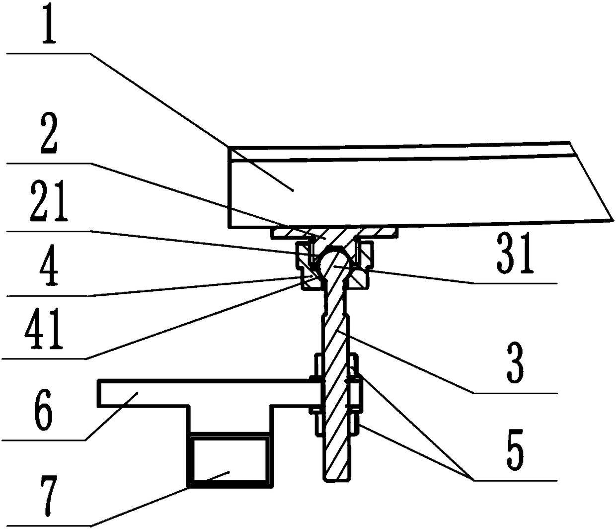
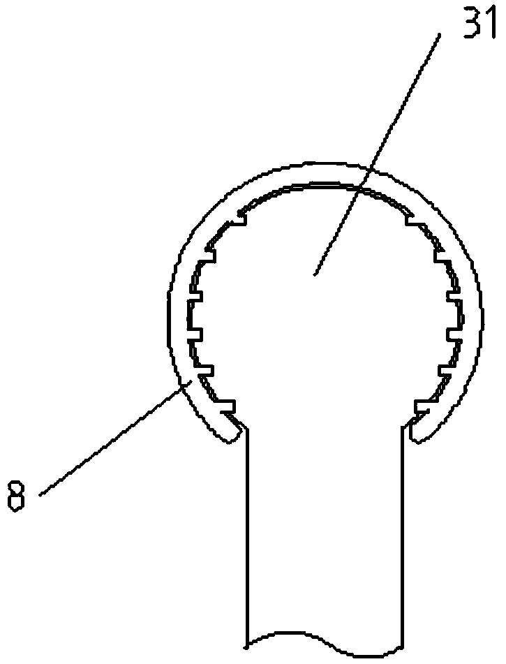
[0018] Such as figure 1 As shown, an antenna panel assembly structure includes a reflective panel 1 and a radiation beam 7, and also includes a ball stud 3, a locking nut 4, a connecting plate 6 and a base 2 located on the back of the reflective panel. The connecting plate 6 is provided with a fixing hole, the connecting plate 6 is fixedly connected to the radiation beam 7, a joint with an external thread is provided on the base 2, and a fastening groove 21 is provided in the joint area, and the locking The inner side of the nut 4 has a fastening contact surface 41, and the locking nut 4 is screwed on the joint of the base 2 through a threaded connection. The fastening groove 21 and the fastening contact surface 41 together form a fastening cavity, The ball head 31 of the ball head stud 3 is located in the fastening cavity, and the screw part of the ball head stud 3 passes through the...


PUM


Abstract

The invention discloses an antenna panel assembling structure, and belongs to the field of an antenna. The antenna panel assembling structure comprises a reflection panel and a radiation beam, and also comprises a ball stud, a locking nut, a connecting plate and a base positioned on the back surface of the reflection panel; a fixed hole is formed in the connecting plate; a connector with externalscrew threads is arranged on the base; a locking groove is formed in the connector region; a fastening contact surface is on the inner side of the locking nut; the locking nut is screwed on the connector of the base through a screw thread connecting mode; the fastening groove and the fastening contact surface jointly form a fastening cavity; the ball head part of the ball stud is positioned in thefastening cavity, and the screw rod part of the ball stub penetrates out of the locking nut to be inserted in the fixed hole of the connecting plate; the ball stub is sleeved with two nuts positionedabove and below the connecting plates respectively; and the two nuts are screwed tightly and relatively so as to enable the ball stud to be fixed with the connecting plate. The antenna panel assembling structure has the characteristics of compact and simple structure, convenience in operation, and accurate repeated positioning, and is suitable for quick dismounting of the antenna panel with relatively high re-assembling precision.

Description

technical field [0001] The invention relates to the field of antenna equipment, in particular to an antenna panel assembly structure. Background technique [0002] The traditional assembled surface antenna mainly includes two important components: the reflective panel and the radiating beam. In the prior art, the connection mode between the reflective panel and the radiating beam is the connection mode of internal taper pin positioning and external nut fastening. It can basically meet the high-precision requirements for reflector antennas. [0003] However, since each panel usually has more than 3 connection points, local stress will be generated during the assembly process of the panel, which will reduce the reassembly accuracy of the antenna, weaken the reflection efficiency of the antenna surface, and limit the antenna accuracy further improvement. Contents of the invention [0004] In view of this, the purpose of the present invention is to provide an antenna panel a...

Claims


Application Information

Patent Timeline
IPC IPC(8): H01Q1/12H01Q15/14
CPCH01Q1/12H01Q15/14
Inventor 陈越杨文宁汪欣
Owner NO 54 INST OF CHINA ELECTRONICS SCI & TECH GRP
Why Eureka
Try Eureka