High-power bipolar pulse formation circuit integrated with high-voltage burst pulse preionization

A bipolar pulse and short pulse technology, which is applied in the direction of electric pulse generator circuit, plasma, and energy storage components to generate pulses, etc., can solve the problems of inability to adapt to changes in plasma load impedance characteristics, large power supply volume, and particle deposition rate. Low-level problems, to achieve the effect of improving power supply efficiency and target sputtering coating efficiency, solving the large volume of power supply, and reducing the volume of power supply

Pending Publication Date: 2018-06-15
INST OF FLUID PHYSICS CHINA ACAD OF ENG PHYSICS
View PDF0 Cites 0 Cited by
  • Summary
  • Abstract
  • Description
  • Claims
  • Application Information

AI Technical Summary

Problems solved by technology

In most cases, a single high-power unipolar generating circuit and a bipolar pulse forming circuit cannot adapt to changes in the plasma load impedance characteristics
At present, the pulse forming circuit with the characteristics of high-power pulse peak and DC form pretreatment can well adapt to the characteristics of load impedance changes. This circuit relies on the DC part to realize the arc pretreatment of the load plasma, and the high-power pulse is used for the target. Sputtering of materials, but because the duty cycle of the high-power pulse is less than that of the DC part, the power supply is larger and the efficiency is lower; the voltage of the DC part is generally relatively low and cannot effectively pre-ionize the plasma load. In practical applications Relatively low particle deposition rate and low target sputtering efficiency

Method used


Image

  • High-power bipolar pulse formation circuit integrated with high-voltage burst pulse preionization
  • High-power bipolar pulse formation circuit integrated with high-voltage burst pulse preionization
  • High-power bipolar pulse formation circuit integrated with high-voltage burst pulse preionization

Examples


Embodiment Construction

[0020] All features disclosed in this specification, or steps in all methods or processes disclosed, may be combined in any manner, except for mutually exclusive features and / or steps.

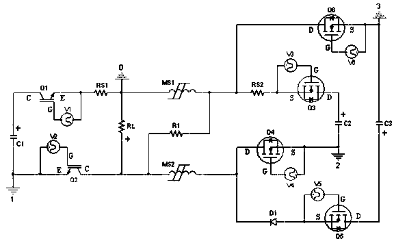
[0021] Such as figure 1 As shown, an integrated high-power bipolar pulse forming circuit integrating high-voltage short-pulse pre-ionization is composed of a negative-polarity high-voltage short-pulse pre-ionization pulse-forming network, a high-power negative-polarity main pulse network and a positive-polarity pulse-forming network. The negative polarity high-voltage short pulse pre-ionization pulse forming network is mainly composed of energy storage capacitor C1, IGBT switch tube Q1, IGBT switch tube Q2, and current limiting circuit RS1 load RL. When the driving signals V1 and V2 are at high level at the same time, the switch tube Q1 , Q2 are turned on at the same time, the energy storage capacitor C1 forms a discharge circuit through the switch tubes Q1, Q2, the current limiting resistor R...


PUM


Abstract

The invention discloses a high-power bipolar pulse formation circuit integrated with high-voltage burst pulse preionization. The high-power bipolar pulse formation circuit integrated with high-voltageburst pulse preionization is formed by a negative polarity high-voltage burst pulse formation circuit, a high-power negative polarity low-voltage main pulse formation circuit, a positive polarity low-voltage pulse formation circuit and a magnistor, wherein the negative polarity high-voltage burst pulse is used to implement preionization processing on a plasma load; and the bipolar high-power pulse is used for sputtering of target materials, thus being able to instantly adapt to the characteristic of load impedance change. In the high-power bipolar pulse formation circuit integrated with high-voltage burst pulse preionization, the output high-power pulse duty ratio is much greater than the duty ratio of the negative polarity high-voltage preionization pulse; the magnetron sputtering and coating power supply efficiency and the target material sputtering and coating efficiency are improved; and the power supply volume is reduced. The high-power bipolar pulse formation circuit integratedwith high-voltage burst pulse preionization is used for solving the problem that the power supply volume is larger, and the efficiency is lower and the target particle deposition rate is low.

Description

technical field [0001] The invention belongs to the technical field of surface treatment research on electronic circuits and magnetron sputtering materials, and in particular relates to an integrated high-power bipolar pulse forming circuit integrating high-voltage short pulse pre-ionization. Background technique [0002] In recent years, magnetron sputtering technology, as a kind of vacuum sputtering, has become one of the widely used technologies for hard coating preparation due to its unique advantages, such as low deposition temperature, high film density and easy control of film thickness. one. Magnetron sputtering technology is divided into DC magnetron sputtering and high-power pulse magnetron sputtering according to the output voltage mode of magnetron sputtering power supply. Because high-power pulsed magnetron sputtering technology has two advantages: high ionization rate of sputtered particles and the ability to deposit very dense and high-performance thin films,...

Claims


Application Information

Patent Timeline
IPC IPC(8): H02M9/04H05H1/24C23C14/35C23C14/34
CPCH03K3/57H05H1/24C23C14/3485C23C14/35
Inventor 李波赵娟李洪涛叶超黄宇鹏张信马勋冯元伟邓维军于治国康传会
Owner INST OF FLUID PHYSICS CHINA ACAD OF ENG PHYSICS
Why Eureka
Try Eureka