Finger joint prosthesis structure

A finger joint and prosthesis technology, applied in the field of finger joint prosthesis structure, can solve the problems of muscle and tendon tissue involvement, failure to reach, dislocation, etc., so as to reduce postoperative complications, reduce the risk of rupture, and achieve reasonable design. Effect

Pending Publication Date: 2018-06-19
TIANJIN SANNIE BIOENG TECH
View PDF0 Cites 6 Cited by
  • Summary
  • Abstract
  • Description
  • Claims
  • Application Information

AI Technical Summary

Problems solved by technology

Second, when the mechanical connection structure rotates, it is easy to involve the muscle and tendon tissue, causing pain and obstruction of movement
The advantage of the non-restricted prosthesis is that the structure of the ball-socket fit is most in line with the nat...

Method used


Image

  • Finger joint prosthesis structure
  • Finger joint prosthesis structure
  • Finger joint prosthesis structure

Examples


Embodiment 1

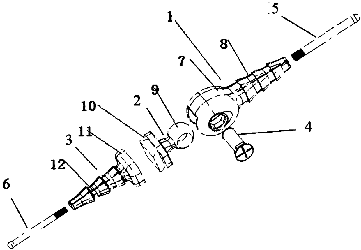
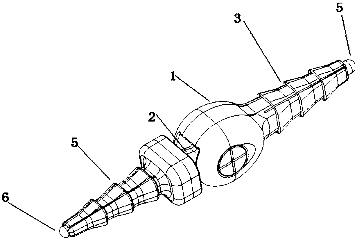
[0039] A finger joint prosthesis structure, including a proximal prosthesis 1, a joint part 2, a distal prosthesis 3, and a rotation shaft 4, and the proximal prosthesis 1 and the joint part 2 form a shaft fit connection through the rotation shaft 4 to achieve flexible joints Rotate to realize that the joint part 2 of the joint is connected with the distal prosthesis 1, the other end of the proximal prosthesis 1 is connected with the proximal expansion screw 5, and the other end of the distal prosthesis 3 is connected with the distal expansion screw 6; the proximal expansion screw 5 and the distal expansion screw 6 are respectively inserted into the medullary cavity at both ends of the joint, and the proximal expansion screw 5 and the distal expansion screw 6 prevent withdrawal.

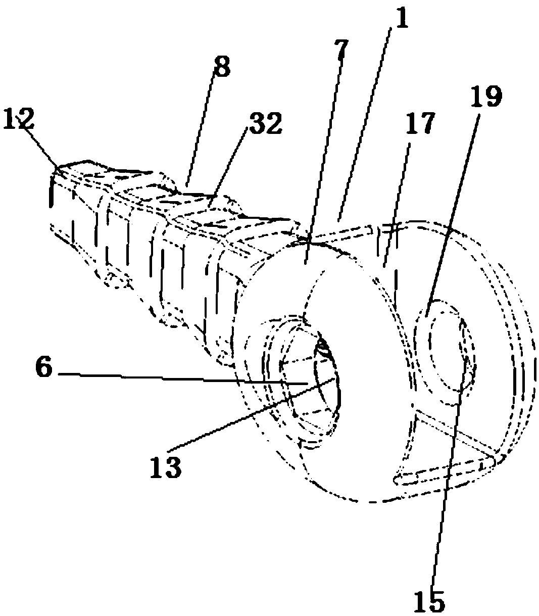
[0040] The proximal prosthesis 1 comprises a proximal prosthesis joint 7 and a proximal prosthesis handle 8, the joint part 2 comprises a joint part head 9 and a joint part tail 10, and the distal pro...

Embodiment 2

[0042] A finger joint prosthesis structure, including a proximal prosthesis 1, a joint part 2, a distal prosthesis 3, and a rotation shaft 4, and the proximal prosthesis 1 and the joint part 2 form a shaft fit connection through the rotation shaft 4 to achieve flexible joints Rotate to realize that the joint part 2 of the joint is connected with the distal prosthesis 1, the other end of the proximal prosthesis 1 is connected with the proximal expansion screw 5, and the other end of the distal prosthesis 3 is connected with the distal expansion screw 6; the proximal expansion screw 5 and the distal expansion screw 6 are respectively inserted into the medullary cavity at both ends of the joint, and the proximal expansion screw 5 and the distal expansion screw 6 prevent withdrawal.

[0043] The proximal prosthesis 1 comprises a proximal prosthesis joint 7 and a proximal prosthesis handle 8, the joint part 2 comprises a joint part head 9 and a joint part tail 10, and the distal pro...

Embodiment 3

[0049] A finger joint prosthesis structure, including a proximal prosthesis 1, a joint part 2, a distal prosthesis 3, and a rotation shaft 4, and the proximal prosthesis 1 and the joint part 2 form a shaft fit connection through the rotation shaft 4 to achieve flexible joints Rotate to realize that the joint part 2 of the joint is connected with the distal prosthesis 1, the other end of the proximal prosthesis 1 is connected with the proximal expansion screw 5, and the other end of the distal prosthesis 3 is connected with the distal expansion screw 6; the proximal expansion screw 5 and the distal expansion screw 6 are respectively inserted into the medullary cavity at both ends of the joint, and the proximal expansion screw 5 and the distal expansion screw 6 prevent withdrawal.

[0050] The proximal prosthesis 1 comprises a proximal prosthesis joint 7 and a proximal prosthesis handle 8, the joint part 2 comprises a joint part head 9 and a joint part tail 10, and the distal pro...


PUM


Abstract

The invention belongs to the field of medical equipment, and particularly relates to a finger joint prosthesis structure. The a finger joint prosthesis structure comprises a proximal prosthesis, a joint assembly, a distal prosthesis and a rotating shaft; the proximal prosthesis comprises a proximal prosthetic joint part and a proximal prosthesis handle part, the joint assembly comprises a joint assembly head part and a joint assembly tail part, and the distal prosthesis comprises a distal prosthetic head part and a distal prosthesis handle part; the proximal prosthetic joint part and the jointassembly head part are in shaft-fit connection through the rotating shaft, the joint assembly tail part is connected with the distal prosthetic head part, the proximal prosthesis handle part is threadedly connected with a proximal setscrew, and the distal prosthesis handle part is threadedly connected with a distal setscrew. The finger joint prosthesis structure has the advantages that a semi-closed structure and a ball-fitting structure are used in joint parts, thereby maximally preventing a muscle tendon from being caught in the rotating shaft to result in a movement disorder when the finger moves, a universal rotation is more accord with the real motion range of small joints of human bodies, the risk of muscle tendon fracture is reduced, the postoperative complications are reduced, andnormal joint functions are better achieved.

Description

technical field [0001] The invention belongs to the field of medical devices, and in particular relates to a finger joint prosthesis structure suitable for performing arthroplasty on human hands and feet. Background technique [0002] At present, joint replacement of large joints such as hips, knees, elbows, and ankles has become increasingly mature, while small joint replacements such as metacarpophalangeal joints are still in the initial stage of development. People suffering from small arthritis, rheumatoid arthritis, and joint deformities in my country mostly do not accept joint replacement surgery. The key reason is that there are almost no domestic knuckle prostheses in China, while imported products are expensive, far exceeding acceptable to the general public. Due to the complex structure of the metacarpophalangeal joints, chronic pain, stiffness, and deformity of the joints lead to weakening or loss of hand function, and knuckle prosthesis replacement is indeed the ...

Claims


Application Information

Patent Timeline
IPC IPC(8): A61F2/42
CPCA61F2/4241A61F2310/00029A61F2310/00023
Inventor 毕思维
Owner TIANJIN SANNIE BIOENG TECH
Why Eureka
Try Eureka